'PANADAPTER'
Last updated March 29, 2016
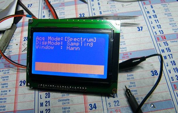
Updated 28th March 2016, Mats reports excellent progress on his new Panadapter PCB's and code. vk3pe is also acting as a beta tester and so far has assembled the display board and part of the main 'DSP" board.
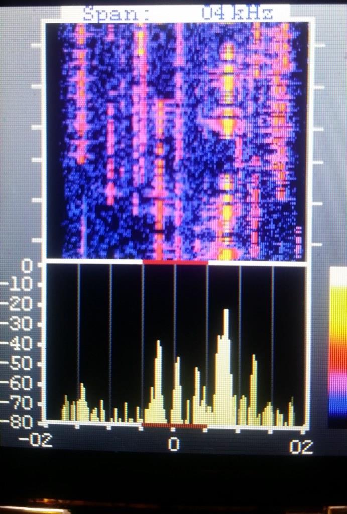
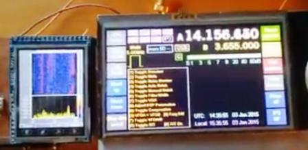
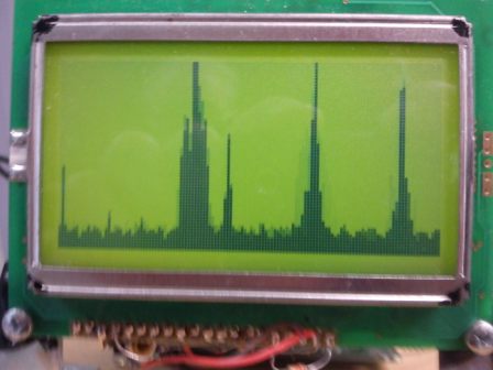
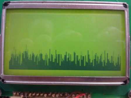
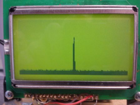
First, here are some pictures of how well the Panadapter works in practice. here it is connected to a Picastar transceiver. [the design features a programmable local oscillator so should be usable on many other Rigs] The pictures show the spectrum zoomed into 4KHz wide in the 40M CW band segment. Note the numner of signals present in the pile-up! The red line at the bottom shows the current Picastar passband settings.
The actual display looks much better than the pictures.
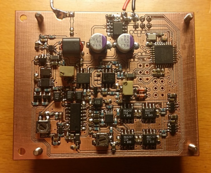
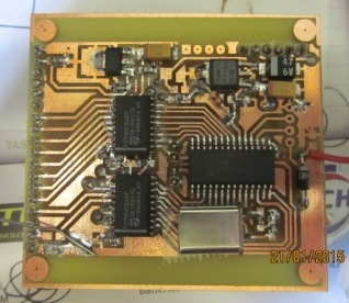
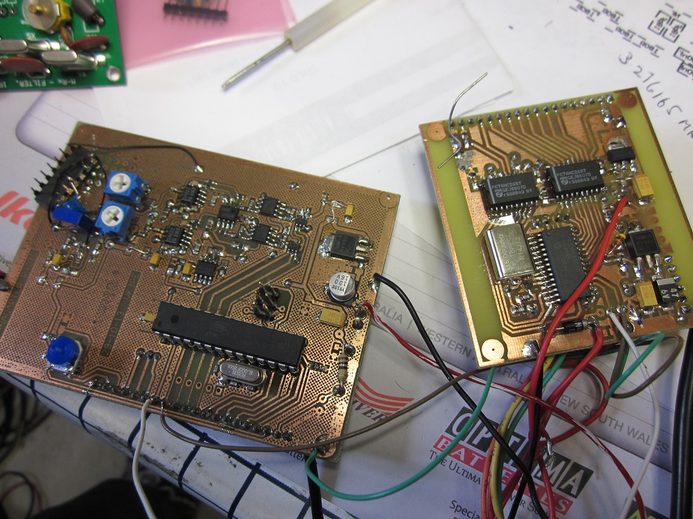
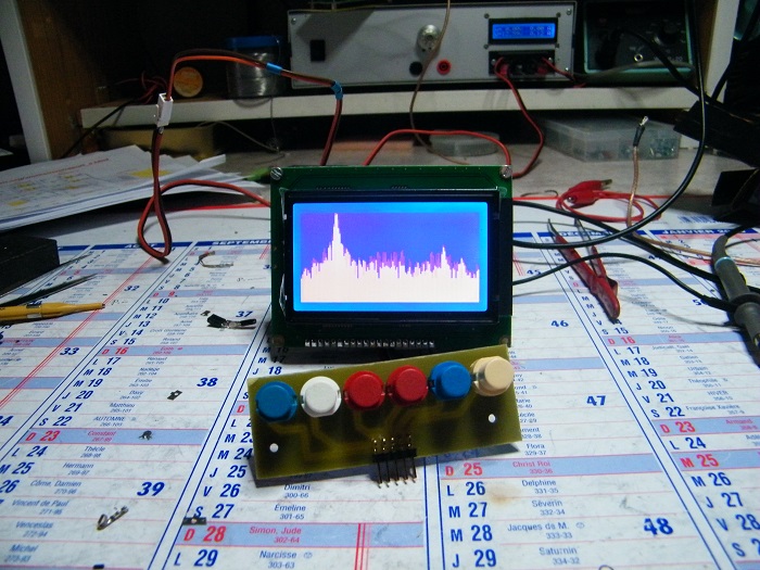
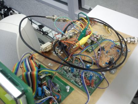
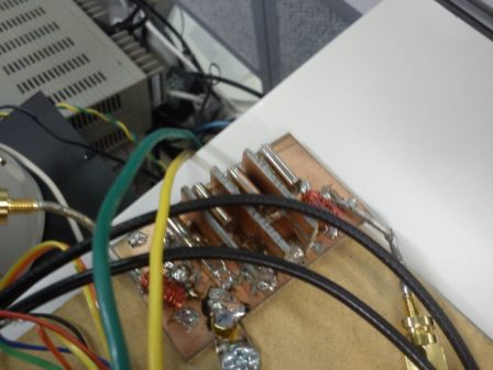
This is the main DSP board built by Mats
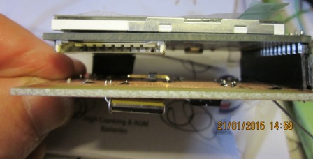
and the display board using a 2.8" TFT built by vk3pe:- The DSP board fits on the top. The TFT is at the bottom, very compact!
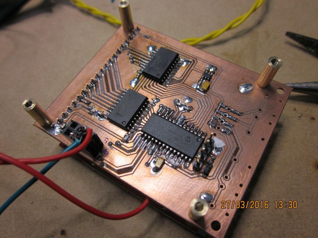
The whole panadapter is built as a 'sandwich' behind the TFT display.
UPDATED Feb 9th 2016, Mats is steadily working on this project and informed me he has a new proto version now running, with all his latest changes.
See above !!
Hopefully I will be able to act as a Beta tester soon. Keep checking this page !
Jan/Feb 2015
Mats, SM0RJV, recently sent me some information on his version of the DSP based Panadapter found on the Web. Mats took an approach to use a colour TFT display by slightly altering the original code, to output high speed display data to a second micro (PIC based) to convert the display data into a colour TFT display format.
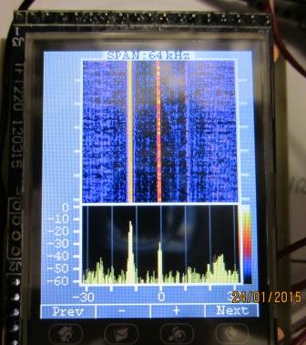
As you can see, the TFT Panadapter (left side) looks great in colour and also has the advantage of a 'waterfall' display. Fantastic!
(This picture is a screen shot of Mats YouTube™ presentation.)
Mats said, when he has documented his project more fully, he will share it with us.
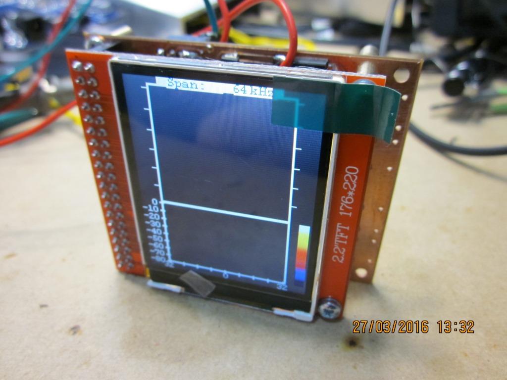
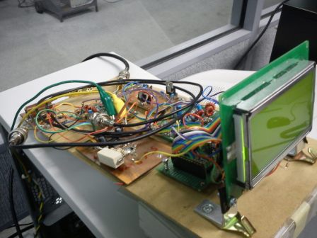
Jan 22nd, 2015:- Mats has kindly shared info with me as a 'beta' builder. I have made up a version of his TFT adapter as below. As you can see, it's working. It's not hooked up to my STAR as yet, just bench testing for now. It is however connected to the Elm-ChaN 'DSP' board (shown further down this page) which uses an AVR Micro, with slightly modified code by Mats. For the PCB below, I am using Mats code in a PIC™ device. The PCB uses easy to obtain parts and, currently, a 2.2" TFT display.
The TFT pictured here has now become a bit hard to find on eBay at least. Another similar type is being investigated, but has a different connector so the PCB shown will be changed to suit, later.
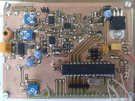
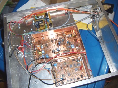
Below:- this the basis of the Panadapter by Mats. On the left is the actual down conversion to I&Q signals (by ELM_ChaN) which are processed by an AVR device acting as a DSP engine. This code has been slightly modified to output the display data in high speed serial form, to the TFT PCB on the right side, which is powered by a PIC device running at 64MHz. Design of the TFT adapter is by Mats, who also altered the AVR code.
NOT shown is the buffer required to bring 455KHz into the board at left, below. The down convertor (mixer) is down this page a little.
The boards in the picture above have been superceded by those at start of this page.
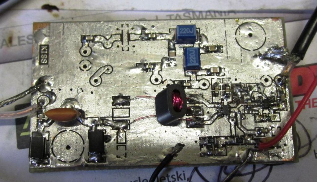
FEB 17th, 2015:- Below is the mixer I am trying. This is the "KISS" mixer (pdf file) by Chris Trask. A very simple mixer to build, although the actual active devices are very tiny. (about 0805 size) They are 6 pin devices, just visible to the right side of the picture below. The input signal at approx 10.7MHz enters via the co-ax cable to the left and travels through a ceramic 10.7MHz FM band pass filter, matched to 50R, to the actual mixer, an FST3157. The transformer is a 4:1 type home tri-filar wound on a BN43-2402 balun core, although this one was not wound per the instructions given by Chris, and results in slightly more loss. Later, the proper winding will be tried. Chris says a Mini-Circuits type can also be used, but is not as good as his home wound version. (PCB pads are for a M-C transformer)
The local oscillator signal enters at the right hand side and the IF out at 455KHz is at the top. There is provision for an MMIC amplifier at 455KHz but it has not yet been fitted, since I don't have a suitable device in stock!
March 2015:- Mats has found another TFT display that is much more easily found (eBay) and less than US$10
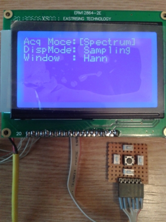
VK3PE has built up the display board and its working nicely. Mats is still to finalise the firmware for this TFT.
More, later...........
Analogue Panadapter !
Peter's Panadapter shown further down this page, is an analogue type, popular in the 'old days' when parts like TFT displays and micros' were not even thought of. It's still possible to build an analogue version but is more work than the one shown above where most of the 'grunt' is done by a Micro.
Analogue versions generally use a superhet receiver to mix down the IF of the transceiver and sweep the local oscillator over a small range and measure the signal strength at each step frequency and use this value to plot on a display. In the old days, this was a tube as used in an Oscilloscope. Now, we can mix technologies and use a TFT display and a Micro to step the frequency using a DDS for example.
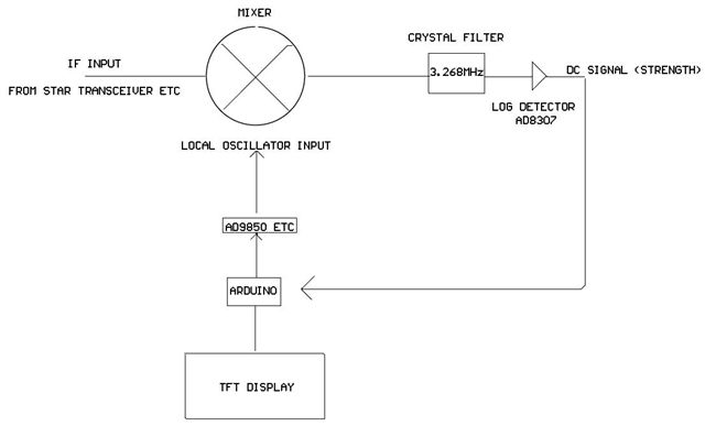
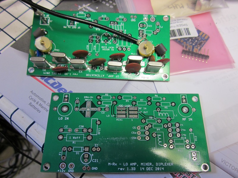
The Yahoo PHSNA group have available a PCB set (picture below) to make a "measurement receiver" that could easily form the basis of a modern analogue Panadapter. They also have an AD8307 detector PCB. Only the crystal filter parts have been loaded in this picture, giving a bandwidth of about 300Hz for the detector. An Arduino micro, a TFT display, and AD8307 log detector are all that is needed. It should be a fairly simple excercise as a Library is avaible for the TFT for plotting and writing scales and text etc.
The Micro would program the DDS (or perhaps Si5351) to step across the frequency range, pause and measure the level from the AD8307 log detector, plot on the TFT, then step to next frequency, etc. In theory almost any scan width could be accomodated using this system, but as one increases the range, the sweep speed would increase. (ie, take longer)
NEW, G4HUP's buffer amp, Jan 2nd, 2014 NOTE:- G4HUP has changed his original buffer to remove one stage, so now has lower ouput level.
Nov 2013:- It's been a long time since I updated these pages from the original notes..
In the meantime, I discovered another PANADAPTER type project on the Web, using a DSP system. This looked appealing and I also mentioned it to VK3ATC, who quickly built one up and is very happy with it. I followed on and have now built a "proto" unit too.
 This is a test only.
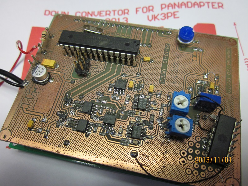 The VK3PE 'panadapter.
73 and best regards,
Cristi YO3FLR
1st December, 2010, See end of page for a working Panadapter !
A "Panadapter" is a device which is connected to a receiver's IF, at a point before any roofing filters. It may then be used to display signals near those to which the receiver is tuned. Of course, a suitable display is required. In the older days of Panadapters, long persistence display tubes were used. In these times, the display may be via a PC or for a self contained unit, some type of graphical display.The horizontal axis is frequency (centered on the receiver's current frequency) and the vertical axis is signal strength, normally calibrated in some fashion. A Panadapter is a form of spectrum analyzer.
These days, there are quite a few small graphical displays available on eBay. In particular, the 128 x 64 dot type are very cheap. Under US$10 if you look around. This is the one I bought, a "Lumex S12864 G". This one has in-built LED backlighting, but more importantly, has its own bias supply. Some displays need external 12 or 13V etc. This one only requires a single 5v supply. It is a little port hungry on a Microprocessor interface though, requiring about 12 lines.
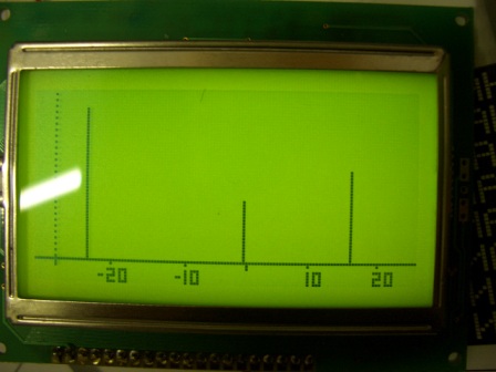
I wrote a quick bit of code to try it out. This represents several signals either side of the centre frequency. At the bottom is a scale with centre frequency and +- 10, 20KHz. This is not the final version. Since there are 128 dots across and 64 down, I have allocated a section to the left (dotted line) of 8 dots across for a scale (not there yet) of signal strength with the bottom 8 dots vertically, being the frequency offset.
I may not use the vertical bar idea but use a single dot for each horizontal point, forming the more usual graphical display for a Panadapter. The exact scaling on the bottom is yet to be determined and is limited by the crystal filter used.
WHERE I WILL USE IT:-
I happen to be be building a PICASTAR transceiver. (See Yahoo groups) So I thought of adding a Panadapter display for it. My thoughts are for the IF signal at 10.695Mhz to be buffered out to a point where, say, an old 10.7MHz 25Khz wide filter could be used. (I have since bought a couple of 10.7MHz, 35KHz wide, 8 pole filters on eBay for AUS$16. Perfect.) Mix this down to maybe 6MHz where cheap crystals are available for a filter to get 200Hz resolution. The filtered output signal can be measured by an AD8307 log detector (or use an FM IF chip with RSSI {signal strength} like the NE604, which is cheaper and easier to get) The local oscillator for the mix down to 6MHz could be done with a DDS controlled by a micro, which sweeps the DDS across the bandwidth of the crystal filter. The micro would convert the level from the log detector using its in-built analogue to digital convertor and then display it on the graphics display.
Here is the bottom of my PICASTAR. Not too tidy just yet as it will be moved into a new homemade box, similar but a little larger than this home made one. The mixer (known as Magic Roundabout) is located at the bottom. The Panadapter will interface to it with a buffer board. Centre is the IF board and above, the T/R timer board.
All of this was prompted by a recent Panadapter article in QEX (I think March/April 2007) and I am about to try an adaptation of this article, using parts to hand, specifically the 128x64 dot graphical display, driven with a Motorola MC68HC908GP32 or QB8 micro. The Panadapter will be self contained, with a (buffered) connection from the PICASTAR IF board, before the 10.695MHz (6KHz wide) roofing filter.
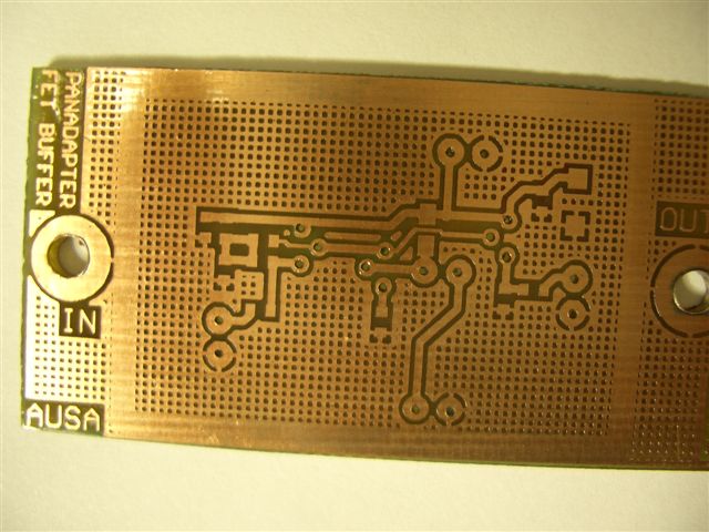
The first thing required is a buffer stage to tap off the IF signal. This should not load the IF stages and it should also provide a low impedance output, for the following stages in the Panadapter. I was looking around the WWW and saw an article on using FET's as source followers. Ref "FET Principles and Circuits, Nuts & Volts Magazine (June 2000), Figure 8." I breadboarded up this circuit for testing: It's not a single FET. It also has a bipolar transistor in the biasing and output stages. It seemed OK, so I etched a PCB for it.
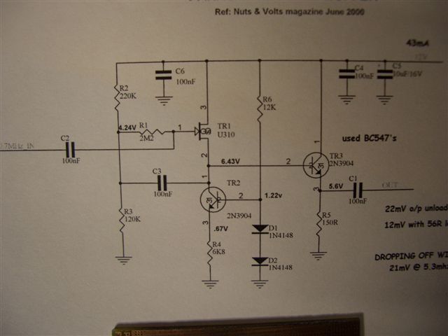 I used BC547's in prototype, but 2N3904's in PCB version.
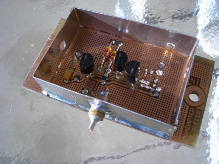
If this buffer proves OK with low signal levels, I will fit it to my PICASTAR, with a co-ax cable and connector on the rear. A shield will be fitted around the PCB. At this stage, the Panadapter will probably be external, but if I re-build my PICASTAR in a new case, I may incorporate it also.
Here is the information for the PCB in pdf format. It's given as is. I have not done any further testing at this stage.
Following the buffer, some amplification may be needed, followed by a mixer, to mix down to the 6MHz filters.. I will use a SBL type mixer initially as its quick and easy. Later I may go to an H mode mixer, as is used in PICASTAR.
NEW Jan 2nd, 2014:- PANORAMIC ADAPTER TAP (PAT). Recently found is this buffer amp by G4HUP, which is also available in kit form.
Refer to G4HUP's web page in link above for schematic and other details. He has a kit available also. This one does have some gain, so maybe more usefull in the DSP Panadapter version. VK3PE has made up his own PCB from G4HUP's schematic. Preliminary testing shows good gain. In fact maybe too much, will see how it performs in the DSP based Panadapter when fitted to my PICASTAR.
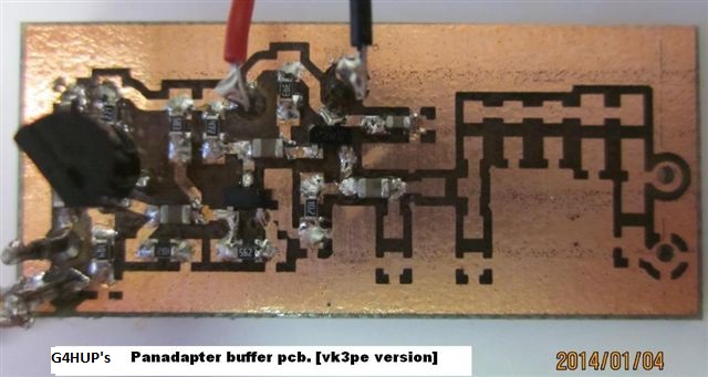
I had to fit a leaded J310, until an SMD one becomes available. Its on the left side of the picture. The other two transistors (BFR92) are SMD parts. The output LPF and attenuator stage is not yet fitted. This PCB is about 1.6" * 0.75".
More later.........
1st December 2010: This is an analogue based Panadapter. Signals off air are down converted and measured for signal strength as the local oscillator of the device is swept across the range in steps. The older panadapters we are all familiar with, used this scheme, as DSP was unknown then ! Its still very effective though.
A friend (Peter) has taken up the Panadapter project and now has a working prototype. Very impressive result.
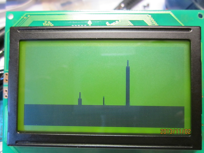
A 128x64 graphic display is used with an Atmel controller. Sweep rate seems very fast so updates are quick.
Below are some pictures of actual on-air signals. There is some 'ghosting' due to the fast sweep and slow camera !
The sweep width is 200KHz......
Above: currently only a 1KHz home made filter is fitted. A 200Hz will be added later.
I will add an IF output on my STAR and try Peters Panadapter in the near future. <vk3pe>
Page created by VK3PE
Updated:- March 29, 2016