The original schematic by Steven, KD1JV, shows the use of a VFO, but in my build, I will be using an Si5351 VFO which is popular these days, being cheap and easy to make using off the shelf Si5351 boards if desired. eg Adafruit™
First thing to do is to make the PCB, then drill it which is a bit on the tedious side but I have a small high speed drill that makes it a little easier, using carbide drill bits.
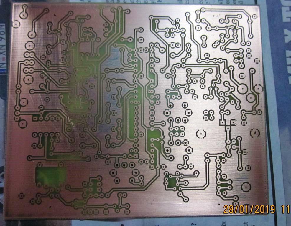
I use a Laser printer to print out the negative, then exposed onto KINSTEN™ pre-coated PCB material. Developed then etched in Ammonium Persulfate. The pcb pattern given, is for single sided PCB only with a number of wire links on top.
Here is the drilled PCB.
Next step is to go through what parts I may need to buy. While I have a pretty well stocked "junque" box, there is always some thing missing. First thing I found is that some of the IC's are hard to come by in DIP package so SOIC parts will have to be fitted with adapter boards. There seems to be some differences to the PCB overlay and the Schematic. eg the "sidetone" trim-pot is not on the Sch. It appears to replace R34 though. The article refers to a parts list "qst-binaries" but I am unable to find a parts list in that document,
The board was designed originally to fit in a plastic case, but no details are given for it. Even so it's hardly likely to be available in Australia. So a home made aluminium case will be made for the project in the interest of DIY !
The IF chosen in the rig is 10MHz with home made crystal filter. I don't have any 10MHz crystals in sufficient quantity, so will use 11.052MHz available cheaply on eBay, plus I already have some of them, enough to select for a filter hopefully.
As mentioned above, I will be using an Si5351 chip for the VFO. It will be controlled by an Arduino NANO™ board and use either an OLED or TFT display. I already have built an OLED version based on the RADUINO style VFO used in the uBITX.
UPDATE 2nd Feb 2019: There appears to be some strange things with the PCB pattern available as a .pdf file for home brewing. One end of R19 should be grounded, the Source lead of Q12 should also be grounded, there's component hole just above D6 that has no connections, ...... more to come......
R12 is missing from the PCB? Possibly goes next to R15........
On the Sch in the pdf file from QST, where are the S1 (CW enable) connection points on PCB?
More soon.........
The inductors used on the board, T1, T2 & T3
It seems the inductors these days are no longer available. I found somebody on the WWW trying to find alternatives. It's suggested that TOKO style be used although they too are hard to find. But often can be removed from old CB radios as a source and then re-wound. The original parts I believe, have a 300 ohm primary and 1000 ohm secondary.
Using this information for Xl, calculates to a 15uH secondary. This would resonate with a 15pF capacitor at 10.7MHz. This though is at odds with the BPF consiting of T2 & T3. The parallel caps. in the Sch are 47pF which is obviously not the same.
I decided to go with a 11uH main winding to approx. resonate with 47pF at 7.1MHz This equates to 26 turns on the TOKO coil former with an AL of '16'.. There is some information on winding TOKO formers here. For the primary I used 3 turns. I used 0.15mm enameled wire which maybe a bit hard to get. If not available experiment with seeing if the turns can be fitted with a thicker gauge.
A quick test of the board loaded only with peripheral parts around T1 and with T1 and U6 fitted, showed that I could peak a signal on pin 1-U6 a couple of turns from the top of the former by feeding a signal in on the end of C27,C51. (I don't have the Tx LPF parts fitted at this point.)
With that done, transformers T2 and T3 were wound in a similar manner.
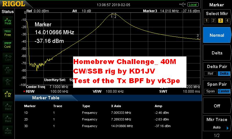
With T2 & T3 now wound as above and other component values around the BPF fitted, the BPF was "tuned up". Since I have an SA with tracking gen. this is relatively simple. The SA was coupled into R11 with a coupling cap. and the output at Q7 Base measured. No DC supply connected. T2 & T3 were then tuned for a nice response on 40M. See plot below.
Looks pretty good actually without adjustment. A slight tweak on T2 & T3 gave the results below.. About 2.5dB loss and band is covered OK. It might change slightly with power on and PTT active. 14MHz is about 37dB down.
Next test is the Tx LPF (Low Pass Filter). I isolated the LPF from T5 and then swept the filter. Initially the loss at 7.1MHz was fairly high, in the order of 5dB. Clearly this is not acceptable in a rig running about 5W of power. I removed L4 and took off 2 turns to move the notch a little further up in frequency. Obviously this is a compromise as now the notch will have less effect at reducing the 2nd Harmonic level.
But, the loss in band has dropped to 1.22dB as you can see. For now I will leave it until actual Tx testing. And see just how good or bad the harmonic levels are.

I think I will have a look at the filter with ELSIE. Perhaps a better filter is possible?
More to come...........
VK3PE
|