N2PK VNA - How it Works

Imagine a simple transmission measurement through a Device Under Test (DUT) on the block diagram. The RF DDS generates an RF voltage at the reference phase of 0 deg, and this signal is applied to the input of the DUT. The output from the DUT to the Detector input is an RF signal with amplitude |VRF| at a phase Theta. In addition, the RF signal at the Detector input is measured with a 'Through' in place of the DUT. The 'Through' is simply a short length of transmission line that is assumed to have unity gain and zero phase. The Detector output is also measured without any intentional RF signal at the Detector input. This test condition is referred to as the 'Open Detector.' For test flow reasons, the 'Through' and the 'Open Detector' measurements are made before the DUT is inserted and measured.

From these three vector measurements at a single frequency, all DUT transmission characteristics, such as gain and phase, can be calculated. Group delay requires two or more frequencies.
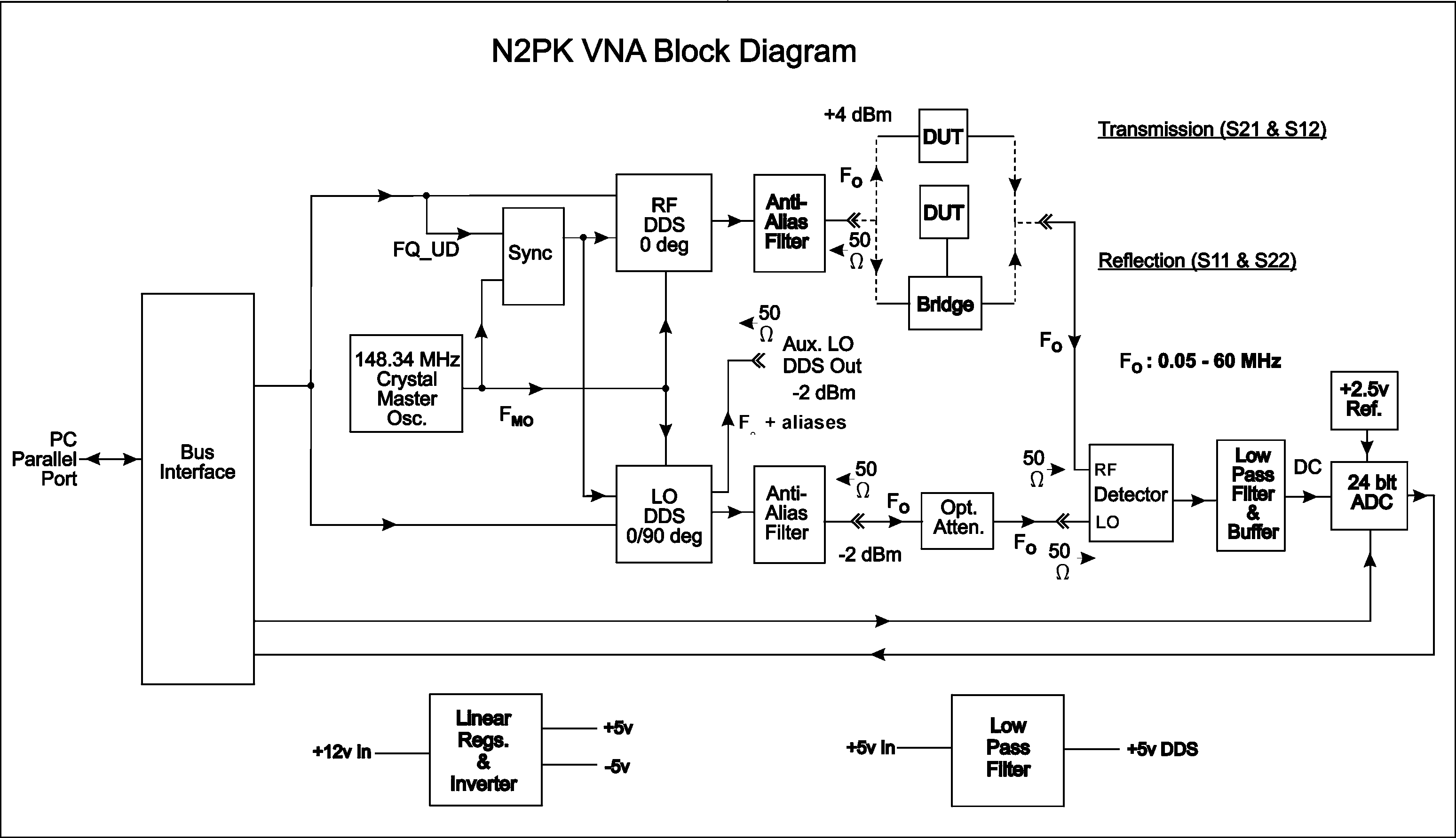
Click to enlarge
(The block diagram can be enlarged for better clarity by clicking on it in an 800x600 window or larger.)

Similarly, all impedance characteristics of the DUT can be measured at each frequency of interest using a standard Wheatstone type reflection bridge. Here, the DUT |VRF| and Theta are measured relative to three precision terminations. The terminations are typically an open, a short, and one that approximates the system reference impedance (usually 50 ohms). These three calibration standards also allow the use of other measurement fixtures (not strictly bridges) that provide improved accuracy for high or low DUT impedances.

|VRF| is quite easy to measure, but there are several different ways to determine the relative phase information Theta.

Most lab-quality VNAs use a superhet architecture that converts both the reference signal and the detected signal to a fixed IF for precision amplitude and phase detection. These conversions occur via conventional mixing or sampling. This architecture, as normally implemented, is complex and expensive. A much simpler architecture is used in the recent 'VNA on a chip' device - the Analog Devices AD8302, with its broadband logarithmic detection of amplitude information and high-speed logic for the phase comparison. The disadvantage here is considerably reduced accuracy compared to a lab-quality VNA.

This VNA is different - it uses a narrow-band direct-conversion architecture that is much simpler than superhet VNAs, but is also much more accurate than the log-detection devices. Because the Detector in this VNA converts down to DC, the only output available is a DC voltage, which is dependent not only on the magnitude of the RF voltage at its input, but also its phase relative to the RF signal at its LO input. Highly accurate measurements of this amplitude and phase dependent DC voltage are obtained using a precision linear analog detector, a 24-bit analog-digital converter (ADC), and precise phase control of the LO DDS.

The phase information is obtained, in a novel way, by making two sequential DC measurements for each frequency and test condition (Through, Open Detector, and DUT). In each case, the first measurement is made with the LO at the reference phase of 0 deg; the second measurement is made with the LO phase shifted by 90 deg. This process results in the quadrature or vector components of each signal at the Detector RF input.

The result is a very simple hardware architecture, which takes maximum advantage of modern developments: the ability of a computer-controlled DDS to generate precise frequencies and phase shifts; precision 24-bit analog-to-digital conversion; and the power of computer control and post-processing. The computer processing completely eliminates setup adjustments, and allows many common sources of measurement errors to be 'calibrated out'. This greatly simplifies home construction.
N2PK VNA Photo Gallery

To see pixs of various builders' N2PK VNAs and links to N2PK VNAs on the web, click here.

N2PK VNA - 'The Rest of The Story'

If you're still reading and interested in more, click on each document or ZIP file named below to either view or download it:
  1. Part 1 PDF (Ver. C, 588 KB)
  2. Part 2 PDF (Ver. B2, 3,690 KB)  Minor correction to pin numbers on U160 in Fig. 1
    The Part 3 PDF, as referenced in Parts 1 & 2, will not be available for some time. However,
    it is not needed to build and use most of the capabilities of the VNA.
  3. VNA PCB 'Build Info' ZIP (Ver. 1C, 839 KB)  Minor corrections to GM3SEK build notes & the annotated images have been deleted due to availability of better images below.
  4. VNA PCB Ordering Procedure PDF (Ver. 2, 24 KB)
    There are changes in this "VNA_PCB_Ordering_Procedure.pdf" that are important ONLY to
    builders that intend to use something other than the ExpressPCB Miniboard service.
  5. Master Oscillator 'Build Info' ZIP (Ver. 1B, 324 KB)
  6. Master Oscillator Test Board 'Build Info' ZIP (Ver. 1B, 99 KB)
  7. Testing of the Fox JITO-2 as the Master Oscillator This oscillator is unacceptable for general purpose VNA usage due to relatively poor phase noise, but could be acceptable for reflection only measurements.
  8. For those builders that do not want to duplicate the homebrew VNA master oscillator or get on some waiting list for a Valpey-Fisher oscillator group buy, there is now a 3rd option in the Connor Winfield CWX823-156.25 MHz. While not quite as good a performer as the Valpey-Fisher VFAC570-148.344 MHz oscillator for phase noise, VNA test results show little, if any, difference between the Valpey Fisher and Connor Winfield parts in the VNA. The Connor Winfield part is also readily available at Digikey. For more on this part, see the "N2PK-VNA" Yahoo group, as described below. VE3IVM's more recent PCBs also support the Connor Winfield part.
  9. T1-6T Bridge 'Build Info' ZIP (Ver. 1A, 172 KB)
  10. VNA PCB, top view, GM3SEK Annotated, Hi-res JPG Photo (Ver. 2, 339 KB)  R120 annotation added.
  11. VNA PCB, bottom view, GM3SEK Annotated, Hi-res JPG Photo (Ver. 1, 364 KB)
  12. Fast ADC & 2nd Detector Overview  This also describes the planned key features of the 'Expanded N2PK VNA' and its planned parallel port assignments.
  13. Fast Detector PDF (Ver. 1b, 442 KB)  This document provides the fast detector hardware update to the original single detector N2PK VNA as well as the dual fast detectors of the Expanded N2PK VNA. With the later addition of the S-Parameter Test Set and new software, the Expanded N2PK VNA will support all of the features shown above in Fast ADC & 2nd Detector Overview
  14. Fast Detector PCB, top view, Hi-res JPG Photo (Ver. 1a, 1,136 KB)
  15. DDS Anti-Alias filter re-design (Ver. 5p1, 90 KB)  This re-design increases the DDS output levels between 50 and 60 MHz while also improving return loss in that range. It is recommended for all new builds as well as retrofitting in existing VNAs.
  16. Single Detector RFIV Test Head (Ver. V1c, 587 KB).  The single detector RFIV Test Head can be used in place of the T1-6T bridge to provide better impedance measurement accuracy and calibration stability over time.
  17. A Simple VNA Transverter (Ver. V1a, 2617 KB).  A simple VNA transverter can be used to extend the frequency range of the VNA in narrow band segments from 60 MHz to over 500 MHz using a bandpass filter and an external oscillator that synchronously mixes the RF DDS signal to the desired frequency range and then back down to the detector RF input. To see Ivan's (VE3IVM) transverter PCBs, click here.
  18. A Relay Based S-Parameter Test Set (Ver. V1a, 261 KB).  A relay based S-parameter Test Set can be used, in conjunction with sofware capable of more sophisticated calibration models, to improve measurement accuracy for two-port networks. To see Gary Johnson's (WB9JPS) test set, click here.
  19. Transmission Calibrations Comparison(Ver. a7, 232 KB).  This document compares several VNA transmission calibration methods and their test results.
  20. Recently there have been some exciting conceptual extensions to N2PK VNA software data collection. As no one document describes these extensions, it is best to join the "N2PK-VNA" Yahoo group (see below) and search its messages using the following terms:
    • CDS
    • Correlated Double Sampling
    • Harmonic Suppression
    • Harmonic Mixing
    An example showing the effects of "Harmonic Suppression" can be seen here.
  21. To see the adaptation of the N2PK VNA to the USB port as done by Dave Roberts, G8KBB, click here. Currently Exeter, VNA4win, and myVNA support Dave's USB interface.
  22. To see Dave's N2PK VNA Debugging Guide, click here.
  23. To see Ivan Makarov's (VE3IVM) VNA PCBs, updated for dual detectors, click here.
  24. Art, KY1K, is also offering parts kits based on Ivan's PCBs. Art's kits greatly simplify the VNA parts procurement process for most builders. For more info on this option, contact Art directly at 'ky1k att myfairpoint dott nett' (correct the obvious errors) or you can also join Art's "N2PK_VNA_Group_Buy" Yahoo group and contact him there. You can find more info about Yahoo groups and joining them below. Art is always interested in reducing the parts cost. In particular, he would like to reduce the cost of the AD9851BRS DDS modules. If you have any info on this or any other VNA parts that might be sourced cheaper, please contact Art.
  25. To see Lawrence's (VE7IT) adaptation of the N2PK VNA PCB to a standalone, reflection only, VNA with its own controller and user interface, click here. To see my version of Lawrence's design as noted elsewhere on this website, click here.
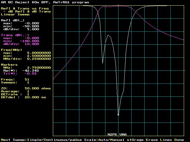
All N2PK VNA software developers are encouraged to support the fast detector and the dual detectors in the Expanded N2PK VNA. The architecture of the dual detector N2PK VNA allows simultaneous real time display of reflection and transmission, as shown here:


When the fast dual detectors are functioning at their faster rates, the combination of simultaneous display of reflection and transmission can be very useful during adjustment of a variety of DUTs.

Also, even without the S-Parameter Test Set which is needed for 12-term error correction, a dual detector VNA can provide improved transmission measurement accuracy over a single detector VNA by being able to account for additional error sources.

Item 13 above shows a block diagram of a VHF/UHF VNA Transverter (Fig. D) that extends the capabilities of the Expanded N2PK to 500 MHz in narrow band fashion. Simpler transverters, compatible with a single (slow or fast) detector N2PK VNA, are shown in item 17 above. All N2PK VNA software developers are also encouraged to support "VNA Transverter mode" or "Synchronous Common LO up/down mixing mode" as it is currently referred to in my software below.

If you print the PDFs, use the "Fit to page" option in Adobe Acrobat Reader.
To download Adobe Acrobat Reader which is needed to view PDF files, click here.
An unZIP program, such as WinZIP, will also be needed.

N2PK VNA Software

First click on one of the README files for software installation instructions and usage of my DOS based software. Then download the software. The PDF has been bookmarked and could be a handy reference.
  1. README - PDF (48 KB)
  2. README - TXT (46 KB)
  3. SOFTWARE ZIP (Ver 2.01, 860 KB)
The above software does not currently support the fast or dual detector VNAs. If you would like a copy of some incomplete beta software, please send me an e-mail requesting it.
Some other sources of software, compatible with the N2PK VNA at various levels, are Windows based and as follows in alphabetical order:
  1. Exeter, by Greg Ordy, W8WWV.
  2. myVNA, by Dave Roberts, G8KBB.
  3. VNA4WIN, by Roger Blackwell, GM4PMK, and Ian White, GM3SEK.
  4. VNAView, by Gary Johnson, WB9JPS. VNAView is available as a stand-alone application and also as source code for National Instruments' LabVIEW.
  5. VNWA, by Tom Baier, DG8SAQ. Tom has added parallel port support for the N2PK VNA plus support for his own VNA in his VNWA program. Make sure that you read Tom's help file to learn how to enable N2PK VNA support.
  6. WINVNA, by Joakim Soya, OZ1DUG.
The following programs can be used to post-process data collected from an N2PK VNA:
  1. Zplots, by Dan Maguire, AC6LA. Zplots is a Microsoft Excel application that accepts data files as input for plotting from my DOS software, Exeter, and VNA4win.
  2. IVManLite, by Ivan Makarov, VE3IVM. IVManLite is a standalone Windows application that accepts data files as input for plotting from my DOS software.

N2PK VNA YahooGroup

A YahooGroup called "N2PK-VNA" has been set up as a forum to aid builders and users of the N2PK VNA.

To simply view the messages, go to:

http://groups.yahoo.com/group/N2PK-VNA/

If you want to post messages, you must get a Yahoo ID by going to:

http://edit.yahoo.com/config/eval_register?.done=http://groups.yahoo.com&.src=ygrp

and then subscribe by either

clicking on "Join This Group!" at the first URL above or by sending an e-mail to :

N2PK-VNA-subscribe@yahoogroups.com

or

Click here to join N2PK-VNA
Click to join N2PK-VNA

To unsubscribe from this group, send an e-mail to:

N2PK-VNA-unsubscribe@yahoogroups.com

German DL QRP Group

There is also a thread in the German "DL QRP Forum" that discusses the N2PK VNA.

To view its messages (in German), go to:

DL QRP Forum N2PK VNA thread

There are also various web based tools, such as Google translate here., that can be used on the above URL.


Back

Please feel free to contact me with any comments or questions at:

Image

73,
Paul Kiciak, N2PK 

URL: http://n2pk.com/VNA/VNAarch.html
Last updated: 20 September 2010
Copyright © 2003 - 2010