VE2ZAZ's, 10MHz, GPS LOCKED PROJECT
Update Jan 2019, new pictures added.
This is a relatively old project from VE2ZAZ, originally published in QEX magazine in Sept/Oct, 2006. It's a very clever take on the work by others including Brooks Shera (sadly, now deceased) to lock a 10MHz OCXO to the 1 PPS signal from a GPS board. VE2ZAZ has full information on his web pages (Google "VE2ZAZ") including the original QEX article, and also provides the HEX file for programming the specified PIC microcontroller (a PIC18F2220) No source code is available and is not needed.
Building this project is made simpler by obtaining the PCB from VE2ZAZ, however as it now transpires, some of the IC's specified as DIP packages in his original work, are a bit hard to get, at least from my usual suppliers, RS-Components or Element14 (Farnell) in VK. Possibly eBay could work here but I am wary of fake parts. To get around this problem, I made my own PCB at home and used all SOIC parts (from RS-Components) except for the PIC which is still a DIP footprint. The PCB pictured is my 1st attempt and could be a little tidier!
One should use the best OCXO you can obtain, but lacking one of the higher end ones like the HP-10544 and 10811 double oven series, I used a smaller Epson Toyocom model OX-6502GG single oven type, obtained from a Hamfest for $10.00. It has very modest power requirments, compared to the double oven HP parts and runs from a 5V supply. My useage for the project will be to lock an HP 225MHz frequency counter and perhaps a signal generator.
VE2ZAZ also provides a Windows monitor program to see how the project performs, called "MONTROL". Download it from his webpage. It's connected to the PC (or Laptop) by a TTL to USB adaptor board, available on eBay. I had a lot of trouble with this, as Windows 10 would not recognize it. I ended up getting a genuine FTDI based board which works just fine.
I used a Trimble GPS module I have had tucked away for some time. It does not output an NMEA string, but that is not important in this project. It does provide the required 1pps output though. (ie 1 pulse per second)
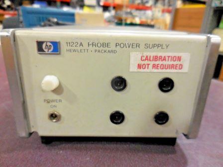
To house the project, I looked in my 'junk box' and found an old HP-1121a Probe Power supply. It seemed perfect for the job, so the internals were stripped out. An "S" shaped chassis was made by bending some aluminium sheet to fit inside. The reason for the odd shape was that the power transformer I had available was fairly tall, so that end of the chassis allows almost full height transformer to be fitted, the remaining chassis is centralised in the case.
The front panel turned out to be perfect for the job. Only one additional hole was drilled, to take the Alarm Reset press button. Four BNC sockets fitted perfectly into the holes vacated by the probe output sockets. The HP badge was removed leaving two holes which were drilled out slightly, to fit the two LED's needed in the project.
At the rear, a hole drilled to take a BNC socket for connecting to the external GPS antenna. The antenna is the type with gain so it requires a 5v supply to be fed up the coax cable. Most GPS modules have this provision.
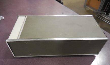
The case I used, before modifying for this project.
Now modified for this project, note the use of existing holes.
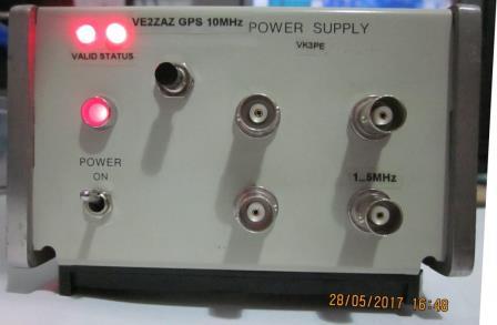 One hole added for push button Alarm Reset. The three un-marked BNC's are 10MHz
output.
One hole added for push button Alarm Reset. The three un-marked BNC's are 10MHz
output.
Home made PCB based on VE2ZAZ's but made for SOIC (surface mount) parts.
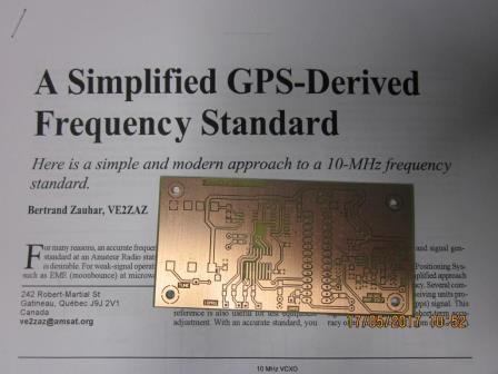 Home made PCB for SMD IC's.
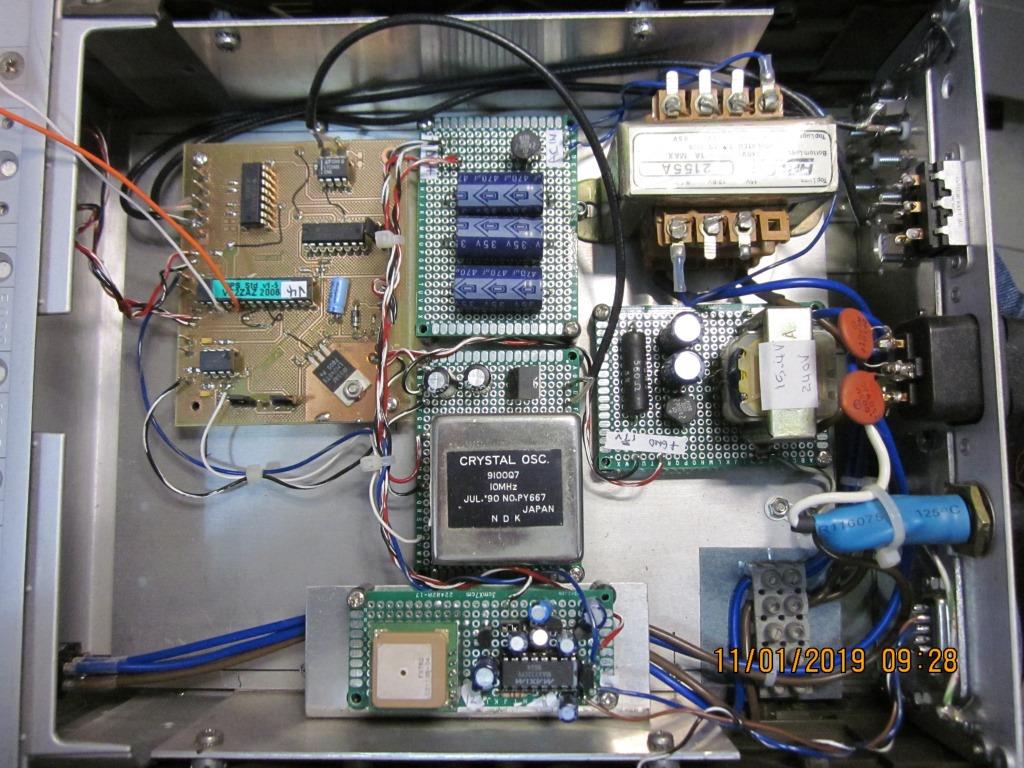
Top view of the project. Note the Trimble GPS module and home made VE2ZAZ PCB. Also the large transformer used, rated at 2A, 7.5V, 0, 7.5V (ie 15V centre tapped)
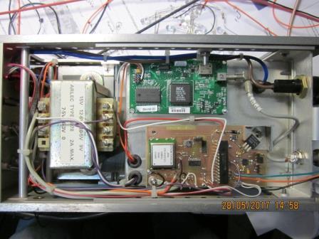 The OCXO is the square package on left side of PCB. It's
a surface mount part removed from some old analogue Cell Phone base stations.
The OCXO is the square package on left side of PCB. It's
a surface mount part removed from some old analogue Cell Phone base stations.
The OCXO used requires about 500mA when cold, settling to about 200mA when warmed up. The GPS and control PCB uses about 120mA or so.
PROGRAMING THE PIC
I used an ATMEL 'ISP3' to program the PIC device from the .HEX code supplied on VE2ZAZ's web site.
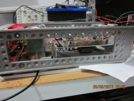 Side view showing chassis.
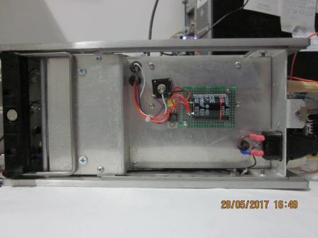
Bottom view. The transformer feeds half (ie two diodes only) of a diode bridge and a 2200uF (105° for longer life, hopefully) capacitor. An LM7805 regulator chip provides a regulated 5V supply for the GPS module only. The VE2ZAZ board has its own 5V regulator which also feeds the OCXO. It would probably be better to have a separate 5V regulator for the OCXO though, to avoid glitches when the Oven is switching on or off..
Rear view is not shown but the existing IEC power input connector and fuse holder are retained. A BNC socket was fitted on the rear for the GPS antenna. The antenna is mounted outside of the shack, on the roof. Make sure you buy a water proof antenna!
View of MONTROL when locked.
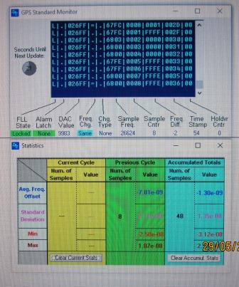 See left centre "FLL State" LOCKED, Alarm latch "NONE",
in Green. "Sample frequency" is 26624, perfect!
See left centre "FLL State" LOCKED, Alarm latch "NONE",
in Green. "Sample frequency" is 26624, perfect!
PRIOR VERSION
I also built another version of this project some years back, (in 2007) when the DIP package IC's were more available. It resides in yet another surplus HP instrument case, larger than the one above though.
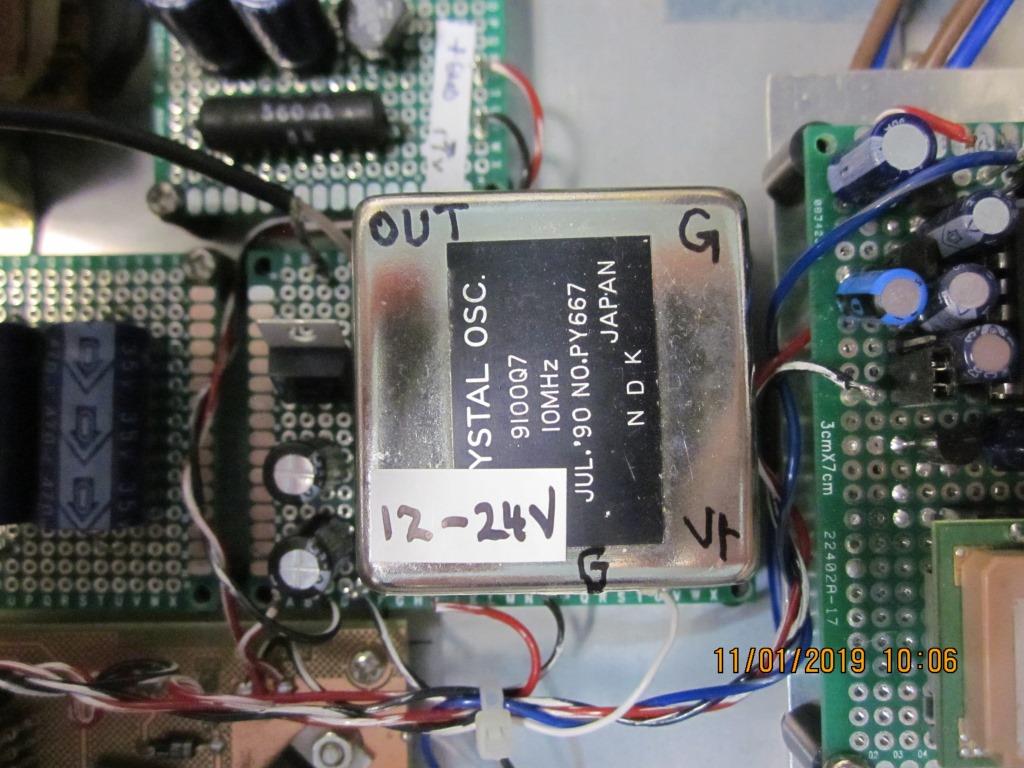
The OCXO used was a double oven type, by NDK, model "9100Q7". It requires a negatve tuning voltage but this is catered for on the VE2ZAZ board, but does complicate the power supply requirements, as three supplies are now required. Namely, -5v, +5v and 12v for the Oven section. Unfortunately I no longer have data for this OCXO but the pin-out is shown below. I run mine with a supply of 12V.
It used an inbuilt GPS board with integral antenna, but in my location, does not lock reliably onto the GPS system, when indoors due to sarking in my roof..
Initially, I had some problems with the software version though, as it would sometimes go out of lock with the tuning voltage stuck at +5V. It had old version (V1.5) firmware and once I re-programmed it to the later V4 firmware, all is good.
This page created by VK3PE (see QRZ.COM) on 29th May, 2017
Last updated on January 11, 2019