

Page Updated
November 20, 2005
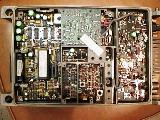
6 meter SyntrxTM Conversion
Many people have asked for details on converting
the Motorola Syntrx (tm) radio to the Ham 6 meter band.
These are preliminary details for converting
a Syntrx (non surface mount components) from the 66-88MHz band to the 52-54MHz
Australian Amateur band. In fact these details for the main board are for the
low range version only of this radio, which is 66-77MHz. Details for the PA
are for both ranges.
Kevin, VK3CKB, (a PA design guru)
has done some more work on the PA and his conversion notes have now been incorporated
into the modification tables.
For the main board, I simply tacked the additional
parts on the back of the board and changed L216. The change to L216 must be
done to improve the pulling range of the PLL. The changed turns on L217 and
L224 must also be made. It's a bit tedious, but possible, to add turns to these
coils.
Of course, the radio's code plug will need
re-programming also. NOTE: The Motorola programming software does NOT
cover the 6 meter band. If there is sufficient interest, I may add the
programming data to this page. Email me
to register interest. Otherwise, see the new micro method.
| Main
Board:- |
Low range |
Hi range
(untried) |
| C3 |
add 27pf |
add 30pf suggested value |
| C5 |
add 27pf |
add 30pf suggested value |
| C7 |
add 27pf |
add 30pf suggested value |
| C10 |
add 27pf |
add 12pf suggested value |
| C277 |
add 10pf |
add 12pf suggested value |
| C281 |
add 27pf |
add 30pf suggested value |
| C280 |
add 10pf |
add 12pf suggested value |
| C245 |
add 6.8pf |
add 6.8pf suggested value |
| Junction of C245 & C244 to
ground |
add 4.7pf |
add 4.7pf suggested value |
| L217 & L224 |
change to 7.5 turn coils |
change to 7.5
turn coils |
| L216 |
change to 1u2 choke |
change to 1u2
choke |
| Power
Amplifier:- |
See table below |
See table below |
| R613 |
remove (lift one
end) |
|
| C612 |
now 47pF, add 10pF |
|
| C632 |
now 300pF, add 68pF |
|
| C630 |
now 300pF, add 14pF |
|
| C634 |
now 510pF, add 150pF |
|
| C640 |
now 220pF, add 30pF |
|
| C653 |
is 51pF Mica |
|
These are the mods to the PA recommended by
Kevin for the Power Amplifier (more details below)
| Component
reference |
Low
range PA |
High
range PA |
| C657 |
changed from 33pF to 47pF |
changed from 27pF to 47pF |
| C656 |
changed from 68pF to 100pF |
changed from 68pF to 100pF |
| C653 |
add 33pF (is 91pF) |
add 56pF in parallel |
| R613 |
lift one end from PCB |
|
| C640 |
|
add 100pF across top original 160pF |
| C632 |
|
add 100pF across top original 220pF |
| C630 |
|
add 100pF across top original 220pF |
| C634 |
|
add 100pF across top original 390pF |
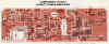 Click to see PA component locations
Following is information from Kevin, on
modifying the Syntrx hi and lo range radios to 6 meters.
It is reproduced as is for your
information. The final results are shown in the table above.
Progress on 6mt
conversion of 66-88MHz Syntrx. Power Amplifier
Glenn,
The first radio I tried happened to be a High range one (77-88MHz), so I was at
a disadvantage to start with. (I noticed an
error on the MB service sheet, it says H
range is 162-174MHz!!). Driving the PA with a Sig. gen gave the following
results
(before any mods). Power supply 13.0v at
radio. Set power to 25w at 77MHz. Sig. gen level +8dBm (PA starts to draw
current at +5dBm or more).
| frequency(MHz) |
52 |
60 |
66 |
77 |
88 |
| power output(J611) |
9.5 |
16.7 |
18.9 |
25.0 |
24.6 |
| Total current(amps) |
5.1 |
5.1 |
5.2 |
5.3 |
5.3 |
| level into RX i/p(dBm) |
+12.5 |
-22.5 |
-19.7 |
-19.3 |
-16.5 |
The high Rx input level at 52MHz indicates a
problem with the antenna switch, NOT to mention the fact that D601 was getting
so hot that it was melting the solder on it's PCB pads. You may be having this
trouble also i.e. with low efficiency due to about 5 watts of power going to
waste heating up D601.
Sweeping from J611 (antenna connector) to the
Rx i/p connector, I made some value changes
C657 = 47pF(was 27pF), C656 = 100pF(was 68pF)
This brought D601 temperature down to OK
level at 52MHz.
Other changes:
Added 100pF across top of the original 160pF
C640.
Added 100pF across original 220pF C632.
Added 100pF across original 220pF C630.
Added 100pF across original 390pF C634.
Added 56pF in parallel to C653 (I scratched off some solder resist on the ground
plane for gnd side, and used C654 input pad for hot side. This gave 2.5w
improvement).
I had to use what parts I have available, which happened to be 0805 SMT Vitramon
Hi-Q ceramic caps in all places. (Surface mount components can be
bought from Farnell and RS Components)
| Result after mods. |
| Frequency |
52 |
52 (reset power to 25W) |
| Power (W) |
21.5 |
25.0 |
| Current (Amp) |
5.15 |
5.5 |
| Rx i/p level (dBm) |
-6.8 |
-1.5 |
The biggest improvement was definitely in modifying the antenna switch cap
values (not covered in your web page), the rest only had a smaller effect. I
didn't try removing R613, and I noticed you reduced C653, whereas I increased
it. Maybe there is some other critical value differences between H and L range
PA's.
Glenn,
Your WEB page assumes a starting range of L-range, eg C640 now 220pF.
A quick way to tell which range Syntrx you have is to look at the value printed
on the side of C653, a
large multi-layer silver mica, located at the edge of the harmonic filter
cover.
It will be 91p for L(66-77), and 68p for
H(77-88) range. I don't know what range radios people have "out
there".
More:-
At 13:25 8/04/00 +1000, you wrote:
8/4/00
Hi Glenn,
I spent a couple of hours after work last night getting a 66-77MHz Syntrx Plus
PA going on 6mt. The PA looks identical to the Syntrx service sheet. In the end,
I only made 4 changes. The mainboard and controller mic. are working OK on this
radio.
Before mods, here is how it worked. As before, the sig.gen drive was +8dBm,
13.0v supply at the radio, and power set to 25w at 77MHz.
| frequency(MHz) |
52 |
60 |
66 |
77 |
88 |
| Power output(watts, |
12.2 |
24.1 |
23.5 |
25 |
17.8 |
| Total current(amps) |
5.8 |
5.8 |
5.95 |
5.95 |
5.7 |
| level into RX i/p(dBm) |
-0.8 |
-14.8 |
-14.5 |
-19.3 |
-15.7 |
As on the H range, I changed C657 to 47p(was 33p on L range). This gave an extra
2.9w at 52MHz(ie 12.2 to 15.1w). Also as on H range I changed C656 to
100p(was 68p on L and H). This gave an
increase to 19w at 52MHz. Also added 33p in parallel to C653(91p on L range). As
before I scratched
off some solder resist on the ground plane for the gnd side, and used C654 input
pad for the hot side. This brought the power at 52MHz up to 24.1w.
I also noticed R613 was getting hot (which is probably why it was lifted out of
circuit on your web notes). I lifted one end, and the power went to 25.3w at
52MHz. (The power does seem to creep up about a watt as the PA warms up, but
this is not a worry). There was probably a good reason why R613 was there in the
first place, such as VSWR stability or low temperature spurii, but I've not done
any such testing. (Increasing the cap across C653 by an additional 30p gave
28-29w, but the antenna switch parts were getting hot again, so decided to leave
good-enough alone. The antenna switch is a Colin special. Maybe he still
remembers how to optimise it).
|
Result after mods:
(re-adjust to 25w ) |
| freq. |
52 |
52 |
54 |
| power |
25.3 |
25 |
27.8 |
| Total current(A) |
5.85 |
5.8 |
5.8 |
| Rx i/p level(dBm) |
-9 |
-9.8 |
-13.2 |
For the L range radio, adding caps across C612, C632, C630 and C634 did not seem
to make much difference as they are large enough already, and not worthwhile.
Also adding an extra 30p to 33p across the 220p C640 to make it about the same
total as on H-range did not give any improvement.
Summary of mods so far.
L-range.
Change C657 from 33p to 47p.
Change C656 from 68p to 100p.
Add 33p in parallel to C653. C653 is 91p on L-range.
Lift one end of R613.
H-range
Change C657 from 27p to 47p.
Change C656 from 68p to 100p.
Add 56p in parallel to C653. C653 is 68p on H-range.
Add 100p across top of the original 160p C640.
Add 100p " "
" " "
220p C632.
Add 100p " "
" " "
220p C630.
Add 100p " "
" " "
390p C634.
(Not sure of effect of removing R613, probably remove to be same as L-range).
Regards,
Kevin VK3CKB
8/12/2000
Here's another variation:-
This information was supplied by VK3TAE BRAD WOODING on converting the MOTOROLA SYNTRX to 6 METERS
The following is to convert a Syntrx low band radio to operate on the 52 - 54 Mhz band.
There are 2 versions of the low band syntrx 66 - 77Mhz (Low) and 77 - 88 Mhz (Hi)
The following is to convert covers both units.
Thanks to Allen Wallace ( Motorola Aust), Noel VK3NH, Kevin VK3CKB and for their input into this document.
Programming.
The proms are: 	20ch	27S571
		40ch	27S573
		100ch	87S185
The radio has to be re-programed. The proms are no longer available so I have designed an adaptor to suit the 2764 eprom.
You must remove jumper JU409 to give you the 100 ch prom option
Circuit Correction
On the Motorola service sheet the PA PCB layout is incorrect. There is 2 C656 cap marked.  C666 is between R622 and R681.
The correct C656 is next to D604. In the RX VCO section C259 is not on the Board layout, this sits next to L224.
RX FRONT END
	Lo Band	Hi Band	6 Mtr Mod	Notes:
C3    	27p	22p	add 27pf across
C5    	22p	22p	add 27pf across
C7    	27p	22p	add 27pf across
C10  	18p	15p	add 27pf across

TX VCO
	Lo Band	Hi Band	6 mtr mod
C245  	15p	15p	add 6.8pf across
C250  	6.8p	------	replace with 12p
L 217	7.5turns	7.5 turns	make 8.5 turns	(Grey taller coil) - 090/039
L 216	290n	290n	Change to 1u2 RF Choke
RX VCO BUFFER
	Lo Band	Hi Band	6 Mtr mod
C277	15p	12p	add 18pf across
C280	15p 	12p	add 18pf across
C281	27p	22p	add 27pf across
RX VCO
	Lo Band	Hi Band	6 Mtr Mod
L 224  			Make 7.5 turns
Use L217 and place in L224 spot as this coil is 7.5 turns already. You only have to rewind 1 coil then. (Violet taller coil) - 070/067
C259 5.6P Not used Add 5.6 across
Change to PA
	Low Band	Hi Band	6 mtr Mod	Notes:
R613	39ohm	39ohm	Remove
C630	300p	220p	Add 100p across
C632	300p	220p	Add 100p across
C634	510p	390p	Add 100p across
C640	220p	160p	Add 100p across
C653	91p Mica	68p Mica	Add 33p for Low or 56 for Hi Band
C656	68p	68p	Change to 100p
C657	33p	27p	Change to 47p
Driving the PA with a Sig. gen gave the following results (before any mods).
 Power supply 13.0v at radio. Set power to 25w at 77MHz. Sig. gen level +8dBm (PA starts to draw current at +5dBm or more).
frequency(MHz)  	52  	60 	66 	77	88
power output(J611)	9.5	16.7	18.9	25.0	24.6
Total current(amps) 	5.1	5.1	5.2	5.3	5.3
level into RX i/p(dBm)	+12.5	-22.5	-19.7	-19.3	-16.5
Surface Mount0805 SMT Vitramon Hi-Q ceramic caps were used.
(Surface mount components can be bought from Farnell and RS Components)
Result after mods.
Frequency		52	52 (reset power to 25W)
Power (W)		21.5	25.0
Current (Amp)	5.15	5.5
Rx i/p level (dBm)	-6.8	-1.5
PA = ALC 6091A 66 - 77Mhz PA = ALC 6092A 77 - 88Mhz
                      IN        /   OUT
JU3     -   	CS       -   PL
JU409    	20CH   -  100CH
MOTOROLA SYNTRX RADIOS Processor Information
INFORMATION SUPPLIED BY BRAD WOODING VK3TAE KEYCOM COMMUNICATIONS
HOME PAGE http://unite.con.au/~ue367/index.html
Last update 21-07-1999
Alterations or additions to keycom@unite.com.au
| MODEL |
uP |
Functions |
| M150 |
51-02060D01 |
|
| M160 |
51-02052D01 |
|
| |
|
|
| Compac |
51-02060D01 |
|
| Compac |
51-02021C01 |
|
| Compac |
51-02051D01 |
|
| |
|
|
| Syntrx |
51-02021D01-A |
Standard
uP |
| Syntrx |
MC68HC705 |
Special
Application |
| Syntrx |
51-02052D01-A |
Decreased
key time, busy light DPL |
| Syntrx |
|
|
| |
|
|
| Syntrx
DVP Multi Scan |
51-02052D01-A |
|
| |
51-0202D01 |
Alternate
Control |
| Syntrx
Base Mic |
51-65020C01 |
Single
channel, no serial data |
| |
|
|
| M170 |
51-02105D01 |
|
| |
|
|
| Syntrx
Plus |
51-02105D01 |
surface
mount version |
| |
|
|
| ATT**WBA*G00AK |
standard
software |
|
| ATT**WXA3G00AK |
DVP only |
|
| |
|
|
Updated June 10, 2002
(hi range main board suggested values added)
REMOVED
NOV 2005
Unfortunately,
some web surfers have expected more than they are willing to give themselves
or are abusive when told there is no information available, so the link to a
very helpful person and web site has been removed!
Xxxx from
company Xxxxxxxxx had gone to the trouble of having a PCB made for the Syntrx
code plug (PROM) programmer. The original programmer was known as the
ASC718 programmer and Xxxxhas made a functional equivalent of this programmer
using the ever popular PIC device.
xxxx also
has the original PROM's for the Syntrx, which suit the above programmer project.
SORRY,
BUT'S GONE!
More info?
Email me
Thanks to VK3NH, VK4TAE and
VK3CKB for their assistance.
Other pages:-


No guarantees are
given or implied as to the suitability of this material for any purpose whatsoever.
Syntrx is a registered
trademark of Motorola.