TrxAVR-Picastar by G3VPX.
These pages are by VK3PE for construction of the TrxAVRB I/F PCB's. Versions "A" and "B"
NOTE: [added Jan 2014]
Drawings do NOT apply to later Combo versions of the PICASTAR PCB where the Trxavr section was either supplied as a small PCB or self contained on the Combo PCB.
(Page format shamelessly borrowed from Ian !)
G3VPX's TrxAVR Interface web pages.
ComboSTAR "B"
TrxAVR-Picastar provides an alternative controller and user interface for a Picastar Transceiver. It replaces "PICnMIX".
Picastar is a very popular HF transceiver designed by Peter Rhodes, G3XJP, for home construction.
Picastar is a Software Defined Radio (SDR) but does not require a PC for normal operation.
Picastar construction information, software, setup and
operational instructions are
available on G3XJP's Picaproject Yahoo Group.
The support group for Picastar is the Picastar-users Yahoo group.
The support group for TrxAVR-Picastar will be the Homebrew-radios Yahoo
group. You need to be a member of these groups.
October 30th, 2009: Version 'B' PCB problem..
This panel is a corrected version. Version "B" (ie most errors corrected BUT unfortunately, the ground missing on IC5 (bottom) is still there. Please check the errors link below for the IC5 problem and how to correct it.)
Page last updated on: January 7, 2014 Minor.
< There are no more PCB's available. >
DEC 14th, 2009:- Gerard has made some excellent progress on the low cost colour TFT. Pictures below.
Nov 13: (cutting the Trxavrb PCB pictures)
9th Nov (4x4 keypad info)
6th Nov (problem with IC5 on Vers B)
Initial build information:
REPORTED PROBLEMS:
Some constructors have reported a few random short (several dots wide) horizontal lines on the 320x240 display.
The solution to this appears to be lowering of some 1k resistor values to 100R. If you have already built the PCB, then changing all of them is difficult. So we suggest you change only the DDS control resistors, R52-54 IC1 pins 26 (PB7), 27 (PH7), 28 (PG3) from 1k to 100R which may well be sufficient. (Gerard)
To remove resistors, 2 soldering irons is the easiest. Just hold each iron on the ends of the part. If you don't have 2 irons, try to heat each end of the part, alternating until the part starts to move.
Or, you could simply fit the 100R over the top of the existing ones.
If you have not yet assembled the PCB, please use 100R for the following resistors:-
Hi Glenn.
I am basing the following on your schematic dated 21-07-09:
R33-34 pins 5-6 (PE3-4)
R36 pin 41 (PL6)
R38-49 pins 42 (PL7),50 (PD7), 51-52 (PG0-1), 53-60 (PC0-7)
R52-54 pins 26 (PB7), 27 (PH7), 28 (PG3)
R62-63 pins 36-37 (PL1-2)
and whatever resistor (if any) is connected to Pad G pin 39 (PL4)
Regards Gerard (vk3cg/vk3grs)
CAUTION NEEDED: If you use the SWR facility, you need to ensure that the maximum output from the SWR bridge will not exceed 5v at the input to the actual Atmega2560 device. (ie junction of R1/R3 and R2/R4) the highest power level you will use, plus a margin. You MUST check this BEFORE connecting to the Trxavrb PCB ! To be safe the maximum output of your SWR bridge is best kept to 5v or you can change the voltage divider values so this maximum at the Atmega 2650 is never exceeded.
Please check here for
Applies to Version "A" only except for the IC5 missing ground. This is also on Version 'B' pcb.
PLEASE read all of this information including link above!
(report any errors or points not clear please to vk3pe#@bigpond.com)
remove the "#" symbol from email address.
NOTE ! See the resistor values detailed at the top of this page.
20-Oct-09 Updated Schematics
16-Oct-09 Bill of Material Ver_7 (_7)
OLD, for reference only:-
31st Aug 2009: Older Schematics
31st August : Click here forOlder Bill of Materials:-_6
BOM covers all options, apart from colour LCD, but must be used with CAUTION at present.
It has been uploaded to give an idea of the parts needed.
Depending upon how you wish to build TrxAVR, not all parts on the BOM may be required.
Parts from www.mouser.com
Notes from Dudley Atkinson: Glenn, I parted out everything for the TrxAvr-B (Ver 6 BOM) at Mouser, with the intention of using the color panel. You might find this list useful to make ordering easy for someone else....
To access your project, click on the url listed below or copy and paste it into your web browser: http://www.mouser.com/ProjectManager/ProjectDetail.aspx?AccessID=536ca8e88f
Or you can access the project by going to http://www.mouser.com/ and click on the EZ Buy option on the top navigation bar.
You can also click on this link or copy and paste it into your browser: http://www.mouser.com/Tools/Tools.aspx. Then enter the following access number listed below into the Project Access ID function. 536ca8e88f
If you would like to add
parts to this project, login to your My Mouser account and then save a
copy of the project. Then use any of these search methods Product Search,
Catalog Browser, or Supplier Line Card to add parts to your project. Once
you locate the product you want, click on the part number. This will take
you to the Product Detail Page where you will see a block called "My Mouser
Project Manager". Enter the quantity you want to add to your project and
select a project name from the drop down menu or select
Component Overlays:
Build information- component overlay (all sections)
All sections, Version "B" NEW 30th Oct, 2009
Build information- component overlay Main PCB
Main PCB, Version "B" NEW 30th Oct, 2009
Build information- component overlay 18 button keypad
Build information- component overlay 8 button keypad
Build information- component overlay Interconnect
Build information- component overlay Atmega programmer
TrxAVR Interface builder's pages.
Feel free to send me your build pictures for display on these pages.
Updated 6th November, 2009
F1CHM, VK3GJM, M1PVC < update 061109, VK3PE,
There's space for you here !!
NEWS:
21st Aug 2009. Gerard and Glenn set up a small display of Picastars with the various displays fitted at a Melbourne radio club (EMDRC). There were some STAR builders in attendance and they were impressed !
General information:
The PCB Panel for this project covers various build options. Read through Ian's web pages for a better idea of what these options are. This project is unlike Picastar in that there are many ways to build the interface, which replaces PICnMIX.
Just how you build the Interface depends on what options you wish to have, including keypad and display types. Depending on how you build the project, some sections of the Panel may not even be required. The Panel contains six individual PCB's.
Please refer to the Bill of Materials (BOM) link above, for a complete list of the parts for a full build of the interface. Of course, you should only obtain or purchase the parts you actually require.
The minimal build is one of the displays shown, plus a keypad, "Menu" and Tuning encoders. The keypad can be a commercial 4x4 type or most likely, the 3x4 keypad plus 6 extra push button switches that can be assembled using the "18 button" keypad PCB included on the panel.
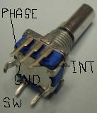
The Menu encoder is a small quadrature type encoder with 2 bit Grey code output, commonly available on eBay™ in "sets" of 10, usually including knobs. (see below) The type from the "sureelectronics" eBay vendor has a large grey knob (usually too large for this project) and the encoders also have a press switch function. This can be ignored or used to replicate the 8 button keypad if space is at a premium. More on this later. An example of this build is here.
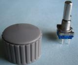
These are sold on eBay in sets of 10 for about US$14
There are others without the switch. They are a little larger.
If you elect to build the full version, with 8 encoders, then the set of 10 above, will be used for this. (You will have one left, as a spare)
You should realize that building TrxAVR with all of the options (depending on display type chosen also) will require a larger front panel then perhaps you already have on a completed PICASTAR. ie you may need to rework your front panel size and possibly the entire housing or case.
Drawings for integration will be added to this page as I have time to draw them up.
However, there is much more information on Ian's web pages which should be read in conjunction with this page, to gain a better understanding of the project.
All programming information is on Ian's pages.
OPTIONS
18 Button keypad
A PCB for this keypad is included on the Panel. I you wish to use a commercial 4x4 keypad instead, then the PCB is not required.
The PCB has been designed to use a commercial 3x4 keypad plus 6 individual press button switches to form the 18 button keypad This is the recommended approach if you don't use a 4x4 keypad. The PCB will also allow the 3x4 keypad to be replaced with 12 individual press button switches if you like. However, this is not recommended since drilling the access holes in the front panel for so many switches, is not an easy task. Drilling the panel for the switches is best tackled by carefully marking out the panel and lightly centre punching the locations for the holes. Then, start with say, a 2mm drill and slowly increase the drill size until the final hole is finished. If you attempt to drill the final hole size without doing this, you will most likely find the hole has "shifted" and also the hole will tend not to be round. I used this method with a battery operated drill, to drill my panel. Patience is needed, don't be tempted to step the size up too fast.
8th Oct, 2009 DIMENSIONS: If you use the 4x3 keypad, then the 6 switches underneath are located as follows:
The top row switch (centre) is 14mm below the edge of the cutout for the keypad. The 6 switches are arranged with a spacing of 14mm across and 13mm vertically.
Refer to the 8 button keypad section below, for details of the cable required.
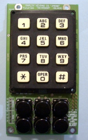
This is my assembly with a 3x4 keypad from my junkbox. The Altronics keypad (VK) is the same, with numbers only. Use small 2mm screws to fasten the keypad to the PCB and fit a nut between the keypad and the PCB to allow the keypad to project through the front panel. A dimension drawing for drilling a panel will be uploaded here soon.
Since keypads vary in pinout, you will need to verify yours from a data sheet or by buzzing it out. Then, short thin wires are soldered to the keypad and passed through the PCB to be soldered to the holes on the left side. The connector is marked with X1 to X4 and Y1 to Y4. "X" of course, is the columns. Don't use solid core wire as it tends to break off.
You may need to file the connection end of the keypad a little to fit on the PCB.
Keypads believed to be the same as the design intent are available from:-
In VK........ Altronics part number S5381 (data) (The Jaycar one is not suitable by the way)
On-line parts company www.futurlec.com Part number KEYPADSM" data sheet here.
In the UK, Maplin part number JM09K
Farnell........ this part 113-0805 seems correct, please verify with Data Sheets !
Also available from Newark in the USA. (unsure of part number)
Possibly Mouser etc in the USA but I have not checked their web pages. Use the data sheet link above for details before you buy.
8th Nov 2009 4x4 Keypad. Paul Craven has some connection information for those in the UK using the Rapid keypad. See Yahoo Homebrew-radios group, msg #3780
8 Button right hand keypad.
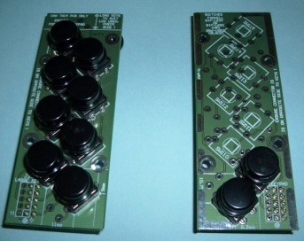
A PCB is included for this option. It uses the same type of switches as for the 18 button keypad. Normally, is it fitted to the right side of the graphics display. If a touchscreen graphical display is used though, the 8 button keypad is NOT required as the touchscreen is used instead. Either type of display though will have the soft keys indicated on the right side of the display. For touch screen, they are pressed for the function assigned. For non-touch screen, eight switches are used. ie the 8 button keypad. However, the 8 button keypad can be replaced by mounting the 8 encoders mentioned above, to the right of the display. The functions are now allocated to the press switch function of the encoders.
The 8 button keypad PCB has been designed to allow the switches to be fitted on both sides of the PCB. It is important to understand why this is so. You will notice that on one side, the keys are spaced closer together. The spacing has been designed to approximately align with the "soft keys" on the right side of the graphical display used. Generally speaking, the wider spacing is the one to use as most builders will be using the eBay white on blue graphical display sold on eBay by the "sureelectronics" vendor. The IDC header is always mounted on the reverse side to the switches.
Below, left, is the shorter keypad loading, other side (reverse side of pcb), part built is the taller loading. Right hand picture shows the connector is mounted on opposite side.
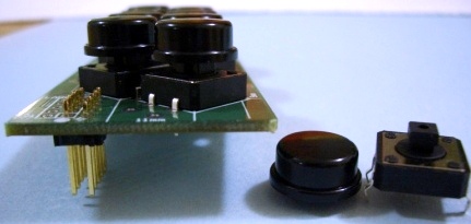
When fitting the switches, ensure they are seated down onto the PCB, before soldering. When inserting the switches, it is simpler if the pins are straightened a little first, with pliers. The switches and caps are available from Farnell™. The part numbers are in the BOM and also on the PCB itself. The caps are available in several colours but I think black is most suitable. Up to you really. In VK, Altronics have these switches and caps also. Jaycar have the switches but no caps and the Altronics caps do not fit.
Connection to the Interface section is via a 10 way IDC socket and ribbon cable assembly. Easily made at home. If you are using both keypads, then the cable will have THREE IDC sockets on it. The central one will connect to the interface board. Make sure you mock up the assembly (ie measure carefully) before making the cable. All of the connectors should be on the same side of the cable. That is, lay the ribbon cable flat and fit all connectors on the lower side of the cable. Ensure pin 1 of the ribbon cable goes to pin one on all connectors. Try to use ribbon cable that has an ID coloured stripe on it. Suitable cable can be found in old disk drive cable assemblies, by the way.
This entire PCB can be replaced with the Encoders with press button switch integrated into them, if you wish. See the section above with the picture of an encoder for more information.
ERROR ! There is an error on this section of the Panel.
Refer to this link for details.
Display type
The interface caters for several types of display, from a simple 4 line x 20 character (or 2x40) LCD display, 128x240 or 320x240 graphics types and also a colour type.
At this stage the colour TFT display is under development by Ian. A mid range (cost) option is the 128x64 pixel display. These are very cheap but having less pixels, the displayed information is restricted, but may suit a PicaStar with a smaller front panel area available. Ian is looking at this option also.
The "sureelectronics" white on blue display is likely to be the most popular, being the cheapest 320x240 type..
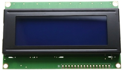 Typical 4x20 Character LCD

ABOVE: Crystalfontz Yellow/Green background not recommended due to high backlighting currents needed. This display is also smaller than the one below. There are also Crystalfontz displays with white on blue, similar to below that ARE suitable. These displays use much less current and are OK to use. They are a little smaller than the eBay Sureelectronics type. See the Bill of Materials.
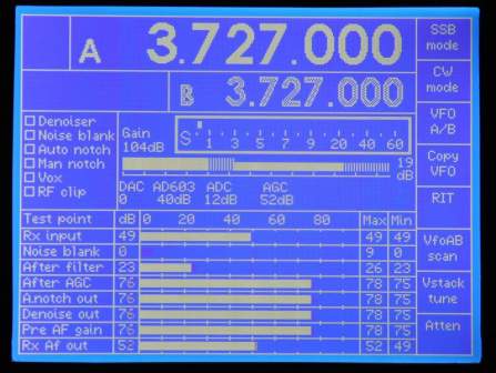
ABOVE "sureelectronics" eBay vendor display. Probably the cheapest of 320x240 types available. Around US$70. Branded as "TOPWAY LM2088S". The vendor has a "data" sheet for it.
It is the type shown above and comes with a small 'test pcb'. NOTE: the display must be the type with the connector at the left side, as per the picture above.
Actual display quality is better in the flesh !
Colour Display: The Ultimate !
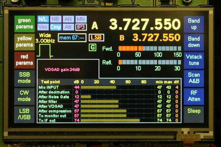
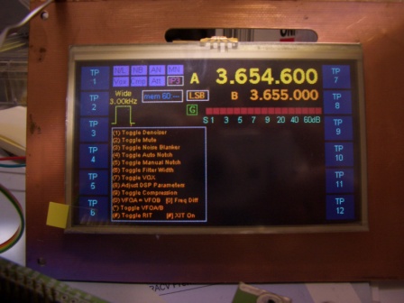
Ian has an ELECTRONICS ASSEMBLY™ colour display (eDIPTFT43-ATP) working {picture below} and you can see more information here. (click back to return here) Note this display has an integrated touch screen hence the soft buttons on the left and right sides. This means the 8 button keypad is not required for this display.
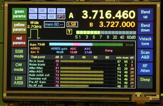
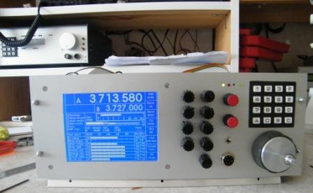
18th Nov, 2009: This is Chris and Gerards low cost display development. Proto only at this stage. Size is identical to the EA one immediately above.
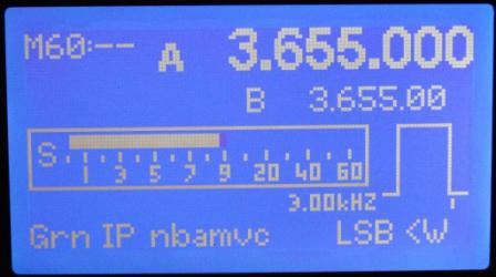
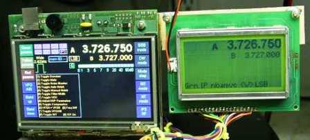 This is preliminary 128x64 display on the right from G3VPX.
There will be other information displayed etc. Below is a white on
blue version of the 128x64 display. (Pics from VK3CG)
This is preliminary 128x64 display on the right from G3VPX.
There will be other information displayed etc. Below is a white on
blue version of the 128x64 display. (Pics from VK3CG)
 I
obtained this 128x64 display (white on blue) from Sure Electronics. The
part number is DE-LM106. This can either be purchased via eBay or direct
from their web store. The buy now price on eBay is $US19.50 and includes
postage. {VK3CG}
I
obtained this 128x64 display (white on blue) from Sure Electronics. The
part number is DE-LM106. This can either be purchased via eBay or direct
from their web store. The buy now price on eBay is $US19.50 and includes
postage. {VK3CG}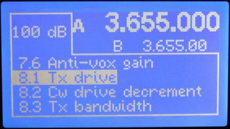
Chris is also working on a cheaper colour alternative but it is early days yet. This will use one of three potential cheaper displays but they require some extra interfacing and software. There are some further details in the link just above.
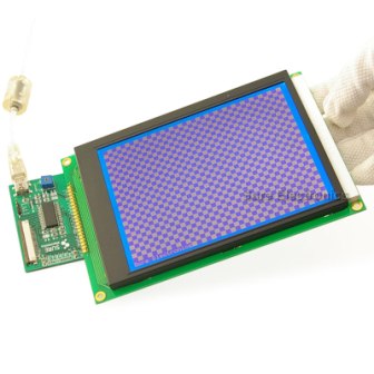
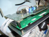
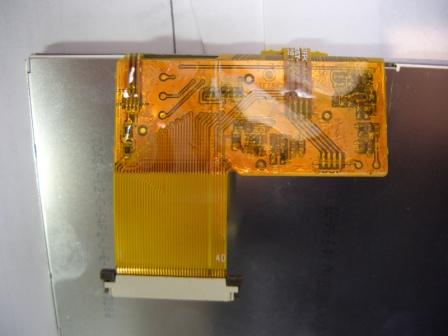 This is the rear of a potential TFT display
that might be used with Chris's interface board. It uses a 40pin FFC connector.
There is another similar display with a 45 pin connector.
DO NOT buy one yet though, as this work is NOT completed.
This is the rear of a potential TFT display
that might be used with Chris's interface board. It uses a 40pin FFC connector.
There is another similar display with a 45 pin connector.
DO NOT buy one yet though, as this work is NOT completed.
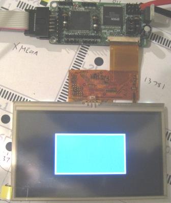
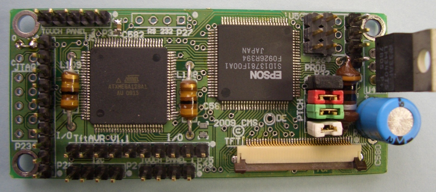
19th Oct 2009:- Click here for a sneak preview of the TFT development work. This is simply a coloured box on the screen but shows that the Epson controller etc is now working. (display still has protective covering on it) A long way to go yet though ! The little PCB (click to see it ) in the screen is a proto only of the TFT interface board, for software purposes mainly. It is NOT available and will change somewhat anyway.
18th Nov 2009:- Gerard has made some excellent progress on the low cost TFT. There are now 3 of these running, but software is not yet completed.
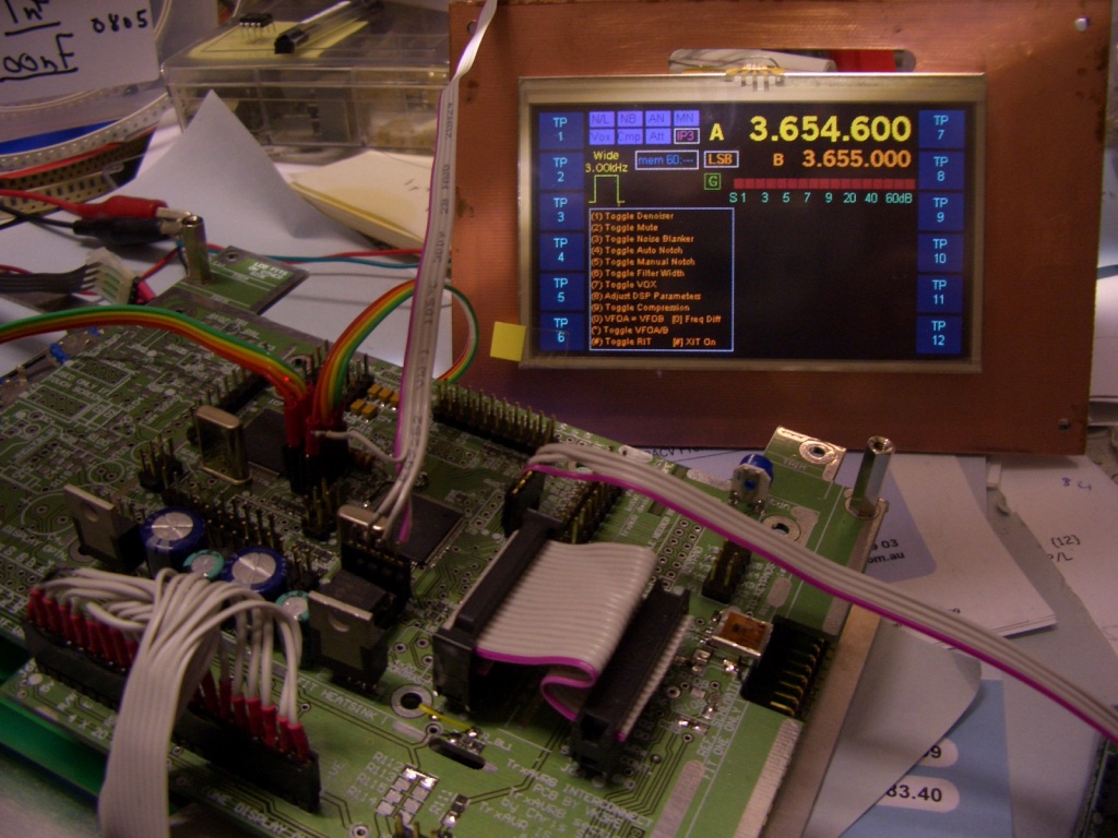 Click for LARGER picture. This is the vk3pe proto unit with "Truly"
TFT.
Click for LARGER picture. This is the vk3pe proto unit with "Truly"
TFT.
Below is Pauls proto: 14th Dec, 2009
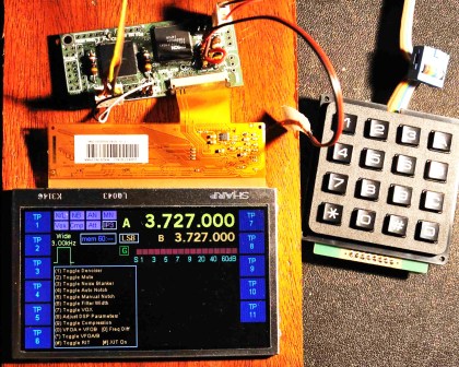 Sharp TFT
DISPLAY CONNECTION DETAILS.
I am working now on the connection details for various displays. Please be aware that I don't personally own all of these types and can't verify their wiring.
The information is given in good faith, but it is up to YOU to double check all wiring against the schematics from TrxAVRB and the Data Sheet for YOUR display. Displays are very expensive. Keep this in mind before you connect and turn it on ! If you are unsure, please ASK on the Yahoo Homebrew-radios group for advice.
Click below for the type of display you have. Make sure it's the right one !
1) 4x20 or 2x40 character based LCD with HD44780 controller or equivalent.
2) 128 x 64 mono Graphics display. Connection details.
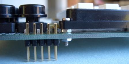
3) 320 x 240 mono Graphics display using S1D13700 controller, or equivalent. eg, TOPWAY LM2088S (available from Surelectronics on ebay or their web site.) To keep the profile lower, it's best to use a right angle header on the rear of this display. This is the display i am using.
 Left is vertical header, right pic is right angle.
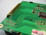
Generic 320 x 240 Graphics displays (other brands etc, you need data sheets for pinouts) Must use S1D13700 controller, or equivalent. Refer to the display data sheet for details.
4) ELECTRONICS ASSEMBLY™ "smart" colour TFT display. (no touchscreen components need to be loaded on the PCB as this display incorporates them already.)
5) Colour TFT interface display by Chris Stake. (work is progressing well on this interface PCB see above) The intention is to make a lower cost version of the TFT above, to suit this project only.
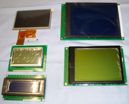 Typical displays. (VK7MX)
Interface PCB section
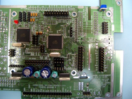
The main section of the Panel is the interface section. This contains the ATMEGA2650's etc. The PCB is shown below as removed from the Panel. You will see that there are several sets of "mounting" holes. These are for the graphical displays (except colour, 128x64 and non graphical displays) eg 4 line x 20 character based LCD's.
Depending on what display is fitted, you may be able to remove some of the "excess" PCB (see "trim" lines on PCB) to reduce overall size. ONLY do this once you are 100% decided on what graphical display you will use.
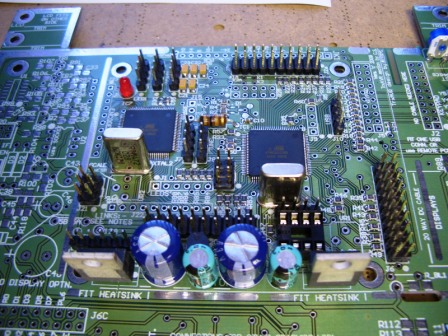
The Interface also contains the touchscreen interface circuitry (to the left side). This will, of course, only be loaded if you have a 320x240 graphical display that has integrated touchscreen. The sureelectronics display does not have touch screen.
There is also an additonal 5volt regulator in this area of the PCB. It is NOT required.
There are 4 mounting holes surrounding the centre section of the PCB. This is where the ATMEGA parts etc are loaded. It is possible to remove this section of the PCB if other than 320x240 graphical displays are to be used. eg colour.
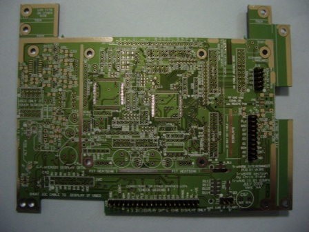
12th NOV 2009. Paul Craven has done this, as you can see below. Click for very detailed pictures (ie larger) NOTE: All parts have not been fitted at this stage.
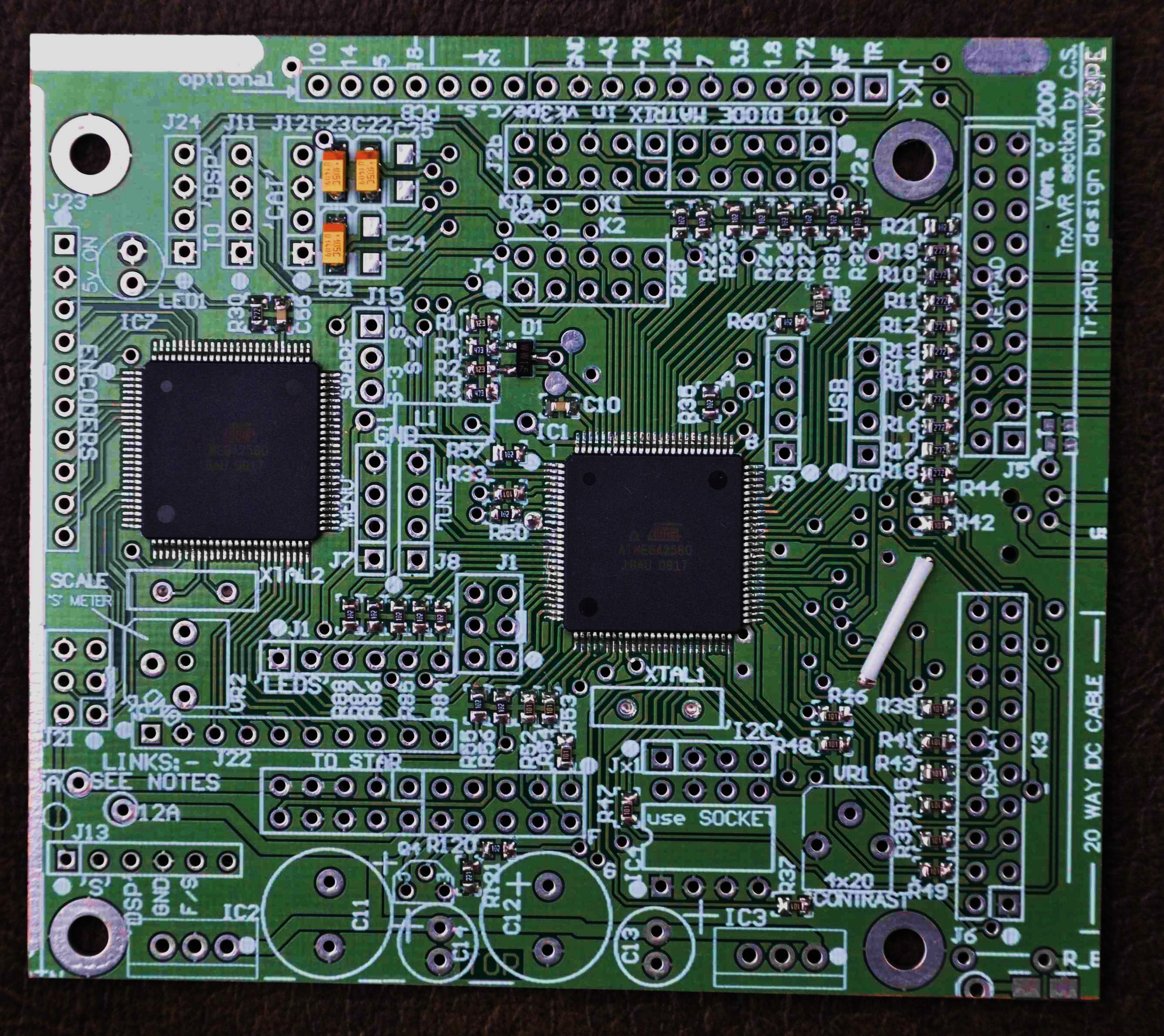 TOP
TOP 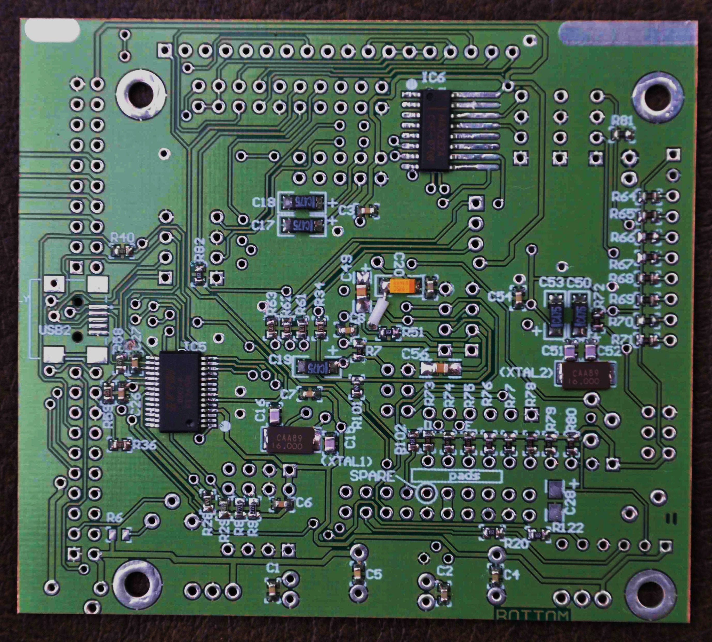 BOTTOM
Near completed:
Removal of this section (and discarding the remainder of the PCB) should be very carefully considered, before cutting ! You will see some non-solder resist areas in the cutting line. There is also a short horizontal slot at the bottom right of this section to ease starting the horizontal cut. This will though, allow a much smaller front panel to be used especially if you are going to use the colour display. The colour display (and other than 320x240 displays) will not directly bolt to the interface PCB. An intermediate PCB (not supplied) may be required. Once this section is removed though, all connections can be made from the various IDC type headers on this section of the PCB. Refer to schematics for more details. If in doubt, please enquire first. (The display connect drawings do not apply if you cut the PCB down. You will need to refer to the schematic for display connection points)
ERROR ! There are some errors on this section of the Panel.
Refer to this link for details.
This PCB is best assembled by fitting the ATMEGA2560 devices first. These have a pitch similar to that of the CODEC and DDS parts in STAR so the same method can be used to solder them. ie solder, then remove bridges with soder wick™.
If you wish though, you could mount all the small SMD parts before the Atmega parts as they should not make soldering the Atmega a problem.
You MUST then check all connections and shorts using the Buzzer board supplied with my Picastar panels or similar. This is the core of the interface and failing to verify this now, it will be impossible to correct later, when all parts are loaded.
This is also the time to decide if you are fitting both Atmega devices. See "Encoders-8".
This is a very tight board assembly in some areas, as you will see.
Please assemble the PCB with patience as any errors will be next to impossible to correct later, in some areas. Ensure you fit the correct part in each position. DOUBLE check !
Print out the overlay and check off each part as it is fitted.
When fitting the supplied 16MHz crystals (which are un-marked), cut a little piece of insulating tape or at a pinch, Cellotape™, and put it on the PCB before fitting the crystal. This helps to reduce the risk of short circuits.
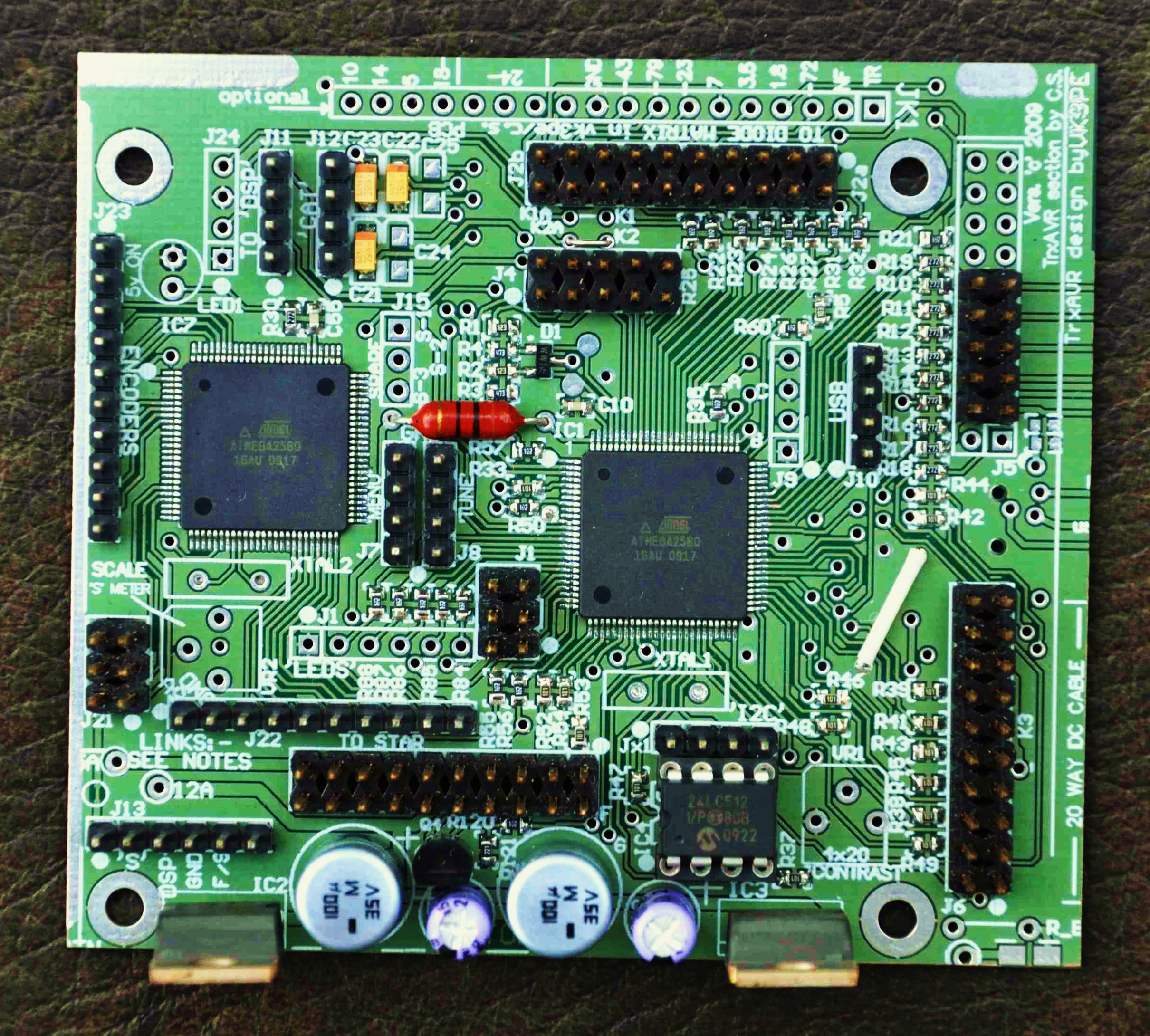
190809:- My build (below) is for an eBay 320x240 display. No touchscreen, so all parts to the left of the central Atmega area are not fitted. Note the dual row headers fitted to the right. The top one (10 pin) is for the keypads. Below that there are two x 20 pin headers. These must be connected by a short IDC cable which I will show later. At the bottom, is a single row connector where my display will be connected via a home made cable to be shown later. A couple of other single row connectors are missing in the Atmega area, at the moment, since I don't have any more stock.
A heatsink for the 5v regulators will be made from a scrap piece of aluminium and fitted next.
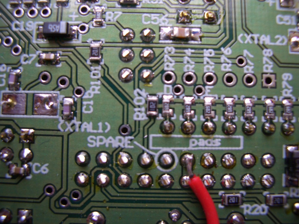 Left: click for larger
picture. 0805 parts can be fitted to what appear to be small pads.
Ensure that the part is centred or prefferably slightly offset to one
side, to leave room to solder the remaining end. This assumes you use
the method for soldering that I do. Lightly tin one pad ONLY then place
the part using tweezers and re-heat the solder to make the joint. Then:
solder the other end. Don't resolder the other end unless absolutely neccessary.
The other parts here are 0603 size which do fit a little easier. The
red wire is the 12v supply input I used for initial testing.
Left: click for larger
picture. 0805 parts can be fitted to what appear to be small pads.
Ensure that the part is centred or prefferably slightly offset to one
side, to leave room to solder the remaining end. This assumes you use
the method for soldering that I do. Lightly tin one pad ONLY then place
the part using tweezers and re-heat the solder to make the joint. Then:
solder the other end. Don't resolder the other end unless absolutely neccessary.
The other parts here are 0603 size which do fit a little easier. The
red wire is the 12v supply input I used for initial testing.
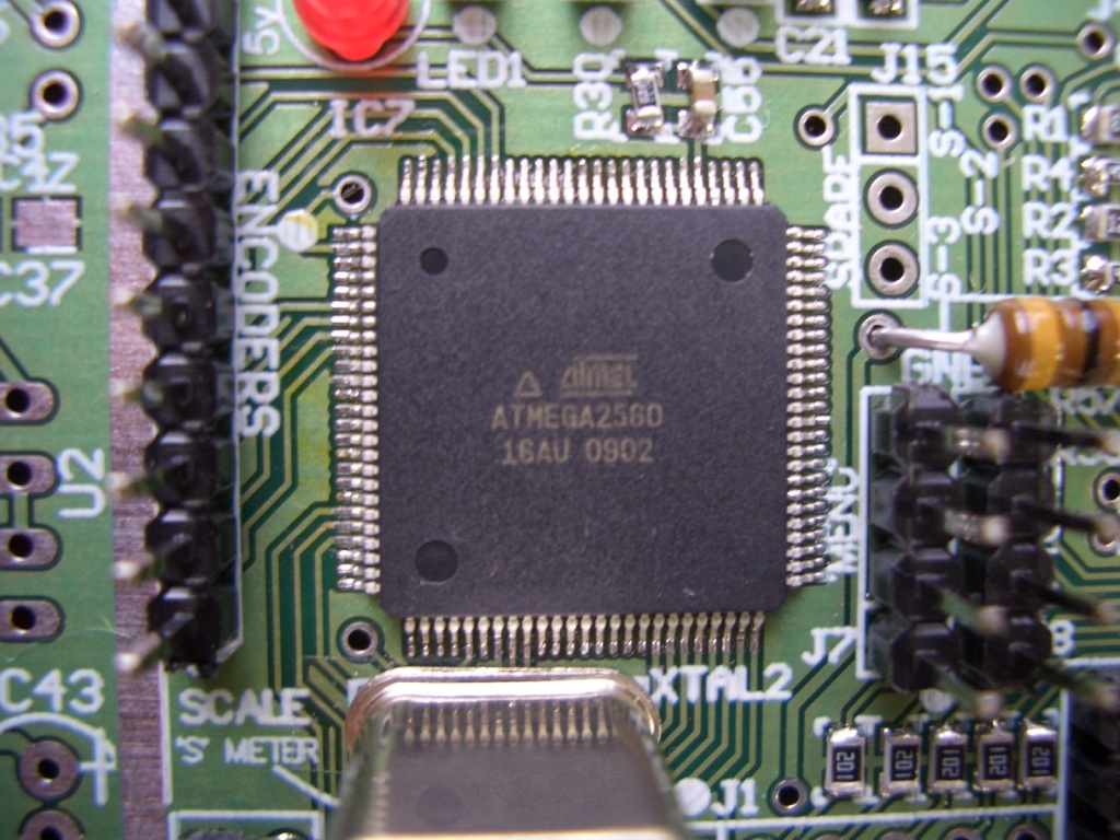 Click for larger picture.
This is one of the Atmega2560's soldered down. Take your time doing these
parts !
Click for larger picture.
This is one of the Atmega2560's soldered down. Take your time doing these
parts !
Encoders-8
TrxAVR caters for the use of up to 8 rotary encoders which maybe assigned in software to virtually any parameter that you wish. Just how many you fit is decided by you. This may be dictated by space available or the wish to have the ability to control less than 8 parameters. Encoders-8 interface is a 2nd Atmega device on the interface board. Even if you don't initially plan to use the extra 8 encoders, it is recommended that the 2nd part is fitted, as retro fitting later would be very difficult, due to the confined nature of the PCB.
210809 Paul Craven has developed some PCB's for mounting the Encoders. See them here.
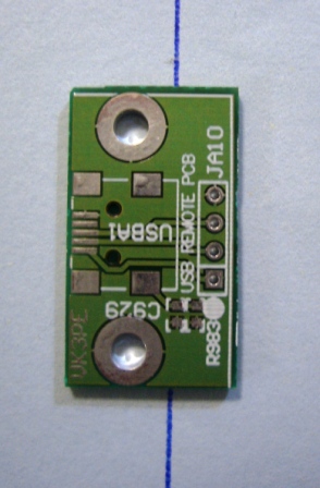
Remote USB
The TrxAVR interface board has provision for a USB (mini-USB) socket for connecting to a PC when using Hobcat. (Refer to Ian's web pages) If you wish to have easy access to this connector, then a small PCB is on the panel, to allow remote mounting of the USB port. A simple 4 way cable will be need to made to connect to it. The PCB has 2 mounting holes but you may need to make some simple right angle brackets, in order to mount it to a rear panel, for example.
MAJOR PROBLEM WITH THIS PCB !
Refer to the Error Link above please for information.
There are also commercially made USB sockets which can be panel mounted. I don't have specific details of brands etc though.
Interconnect PCB
This is a small PCB that has been provided to assist in the integration of this project into PICASTAR. The TrxAVRB interface has a number of connectors for interfacing to the various options, plus to PICASTAR itself. For PICASTAR, there are two 20 pin IDC headers and the simplest method is to make two 20 way IDC cables that connect from the TrxAVRB to the Interconnect PCB. This PCB is mounted in a convenient location in PICASTAR then wires are made off to appropriate points in PICASTAR. If required, the interconnect PCB can be cut in half by the user at the marked points.
Use the integration drawings I provided on the Picastar pages to understand what is connected. If your Picastar is already built, then you should be familiar with this. Check the Builders links for VK3GJM at the top of this page also. Gerald has used this PCB and it is visible in the pictures. Click on the picture for a larger view.
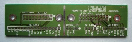
For vk3pe's ComboSTAR, (single board version of PICASTAR) this interconnect PCB is not required. ComboSTAR has been designed so that the two 20 way IDC cables from TrxaVRB simply plug directly into the Combo PCB.
Volume Control
TrxAVRB interface allows a standard potentiometer to be fitted, to control the audio level. Details on Ian's web pages.
Atmel Programer
This is not really an option. This PCB must be built in order to program the Atmega2560 devices on the interface, unless you have a suitable Atmel programmer already. You will need to assemble a 6 way IDC cable also, to connect the programmer to the Interface board. There are 2 Atmega devices on the Interface. Both must be programmed (with different software)
The programmer board included requires the downloading of "PONYPROG" software (Ver2.07c or later) from the Internet. You will need a serial port on your PC also. Details and link are on Ian's web pages or see here. Note that there is a patch for this program, on Ian's pages which must also be used.
A 6 way IDC ribbon cable needs to be made also. You will need 2 x 6 way IDC (dual row) sockets and some ribbon cable about 200mm long.
Peak SWR
Ian's software also has provision for a SWR function. This PCB is not included on the Panel due to a lack of space. If there is a demand for this, a group buy will be investigated. Ian has information though for home-building this PCB on his web pages.
LINKS
Ian, G3VPX's web pages.
Ian's pages have full information on this project including the Atmega code and Hobcat downloads. Ian's pages should be used as the reference for the build.
Ian also provides a step by step guide to programming of the Atega2560 devices using the PONYPROG program. Also, the full setting up of the interface options using Hobcat.
Please make sure you read through Ian's pages and try to understand the process.
Click here for G3VPX's TrxAVR Interface web pages.
Created by VK3PE
August, 2009
Click for for more details.