 Here is the DSP
Mother board. The Left hand connector yet to be fitted.
Here is the DSP
Mother board. The Left hand connector yet to be fitted.DSP Motherboard
Last updated on:- August 12, 2008
DSP M'bd overlay here "Update-1" clearer picture 12th Aug 2008
Schematic here "Update-1" 23-11-07
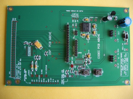
Here is the DSP
Mother board. The Left hand connector yet to be fitted.
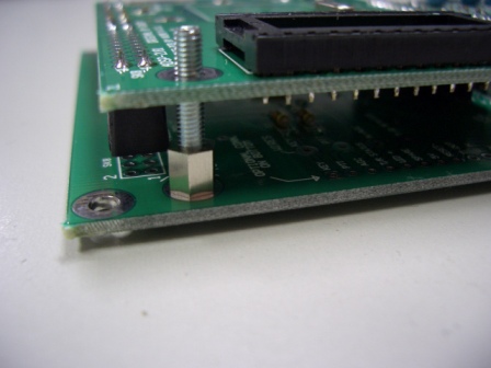
Only the active pins need be fitted.(See below) A 3mm diameter x 20mm long screw should be fitted through the location hole at lower left. This helps to locate the DSP board when it is plugged in. See picture below.
31-10-07 The MAX232/ST232 should be the wide type eg MAX232EWE or CWE. This is the most common type. Personally, I have never seen the narrow SOIC part but make sure you get the MAX232EWE or CWEpackage. (The "E" means extended temperature range, C is commercial)
23-11-07 The value of R90 is too low to allow the next stage to drive the front panel DSP LED. Change R90 to 3k3 (3.3k)
 A view
of the part-built DSP assembly. You only need to fit the header pins on the
dual row section for the DSP that are actually used. I used two rows of single
row header pins. Similarly, on the DSP board, only fit the sockets needed. I
used two rows of single row sockets to make the dual row. See pictures below.
A view
of the part-built DSP assembly. You only need to fit the header pins on the
dual row section for the DSP that are actually used. I used two rows of single
row header pins. Similarly, on the DSP board, only fit the sockets needed. I
used two rows of single row sockets to make the dual row. See pictures below.
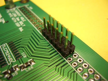
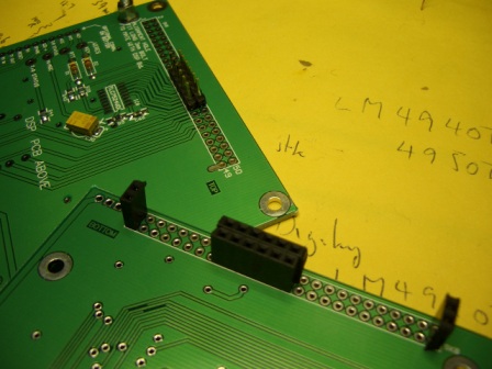
This is the bottom of the DSP board. I decided to fit 2 pins at either end also, to aid in location. (That's my doodling on the Audio chip on the background) The end and central connector is made up from single row PCB socket connectors.
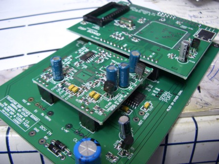
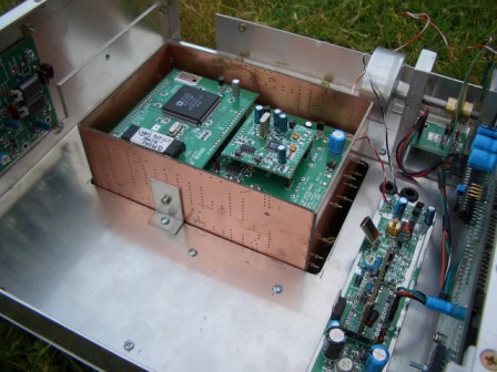 DSP/IF block mounted in my chassis 18th Nov 07