Diode Matrix & Audio Amplifier board
06-12-07 There's a mix-up in the labelling of JP503 pinout for the LPF. Details below.
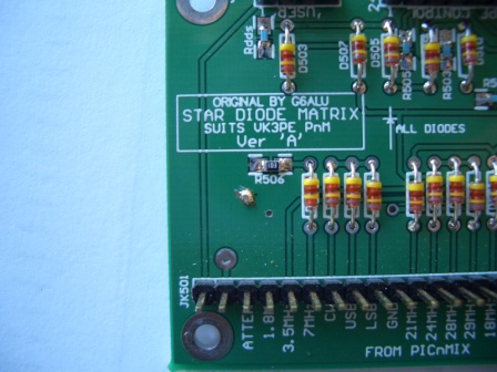
02-03-08 A problem found by Paul, the resistors have no ground even though the PCB package says they do! Connect one of the resistors (R506)to gnd with a wire to JK501-10 or drill a small hole thru the PCB at the R506 gnd point, insert and solder a wire to both sides.(scrape resist off first) See centre of this picture, just below R506.
05-05-08 Glenn, For the diode matrix, to ground R506, I ran a piece of wire wrap wire through the via above pin 2 of JK501 and then connected it to pin 10. No drilling required. Hans
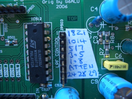
I fitted a sticky lable to show the changes to the connector.
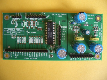
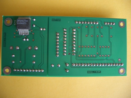
Matrix and AF amp built, less the diodes.
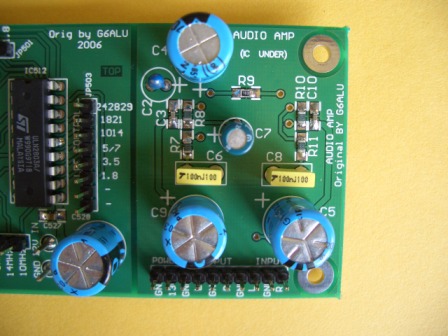
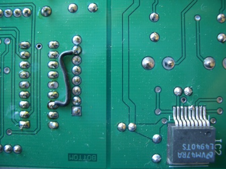
 This
is the rear of the board. The mounting lands on the PCB are a little short for
easy mounting of the amplifier IC. It would be easier to assemble if you
trim about 1mm from the ends of the leads of the IC before placing the IC onto
the PCB. Note it has NOT been done in the picture!
This
is the rear of the board. The mounting lands on the PCB are a little short for
easy mounting of the amplifier IC. It would be easier to assemble if you
trim about 1mm from the ends of the leads of the IC before placing the IC onto
the PCB. Note it has NOT been done in the picture!
Later...........
I connected 12V DC power to the Audio board (observe polarity as no protection) and the standing current was 18mA which is about what the Data sheets says. (Typical 16mA) Connecting a speaker to a channel and placing a finger on the input terminal, I can hear hum. Appears the amplifier will be OK.
There is an error in the labelling of the LPF connector, JP503. Bands are offset on the connector.
You must read this and make corrections to your PCB. You don't have to fit the link as suggested, as you can pick up the 24, 28, 29 band from the BPF connector but the change makes it easier to wire to your LPF board.
NOTE: pictures above do NOT show the changes.
Corrected Component overlay here 06-12-07
Corrected Schematic here 16-06-08 correction to AF amp IC pin name also.
Component overlay (uncorrected) here for reference only.
Schematic (uncorrected) here for reference only
August 2, 2008