
home
Raduino and Si5351 PCB's |
The "RADUINO" board was originally designed by Ashar Farhan, VU2ESE, and is part of the uBITX project. See http://www.hfsignals.com/index.php/ubitx/ The Raduino board alone, is a nice project for anybody who requires up to three frequencies for their own rig, other than the uBITX. Typically as a VFO and BFO for example, which uses two of the outputs. I'm a Amateur Radio operator (VK3PE) who loves to build 'stuff', typically HF rigs, and the Raduino is very suitable for these projects, when the complexity of other approaches is not warranted. Or cost is a major consideration. There are others who have made a version of the Raduino also with various additions or enhancements. A Google™ search will find them. This is my version, which also uses a plug-in Si5351 PCB rather than being self contained as in the original Raduino. |
| Last updated:-
October 10, 2021 |
When I do a project I usually make a PCB at home for the job. If I think the board maybe useful for other projects sometimes I get a small batch made in China.
I originally started this project with the Si5351™ board. The Si5351 board is made by Adafruit™ among others, but my needs went a little further. The Adafruit board has no buffering on the outputs. There is a lot of discussion in various Web groups about the Si5351 and the cross talk between outputs due to a common power supply pin on the Si5351 device. When outputs are loaded. So, I decided to make my own Si5351 board and add buffers to each output and also to decouple the supply to the buffer chips with an LC network on each of the supply pins, in an effort to hopefully reduce this. See report below.
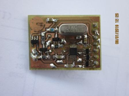
This is my home made Si5351 board.
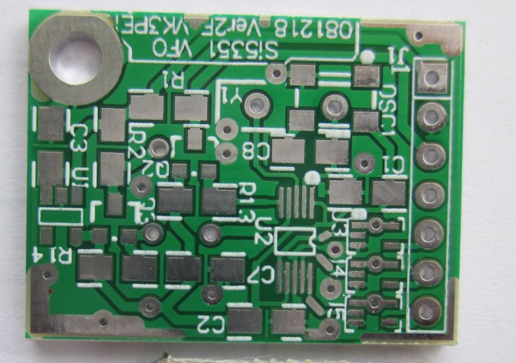
And here is the "proper" PCB I had made. It's 32x22mm in size. It's a little tricky soldering smd parts on a home made pcb as it's easy to get shorts. The "proper" PCB is much better in that regard and looks pretty too! Parts used are 0805 in size. 1206 will fit also. Don't be frightened by the use of smd and small parts. I'm in my 70's and solder these boards without asistance except for a magnified lamp. Soderwik(TM) comes in very handy for shorts and also the use of a flux pen (they look like a marker pen but have liquid flux inside) is the key probably to doing this.
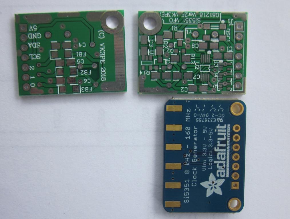
And a comparison with the Adafruit version. Pin-out is identical. As you can see, orientation is different.
And fully loaded. The buffers are the 3 small chips adjacent to each other. Filters to each are on other side.
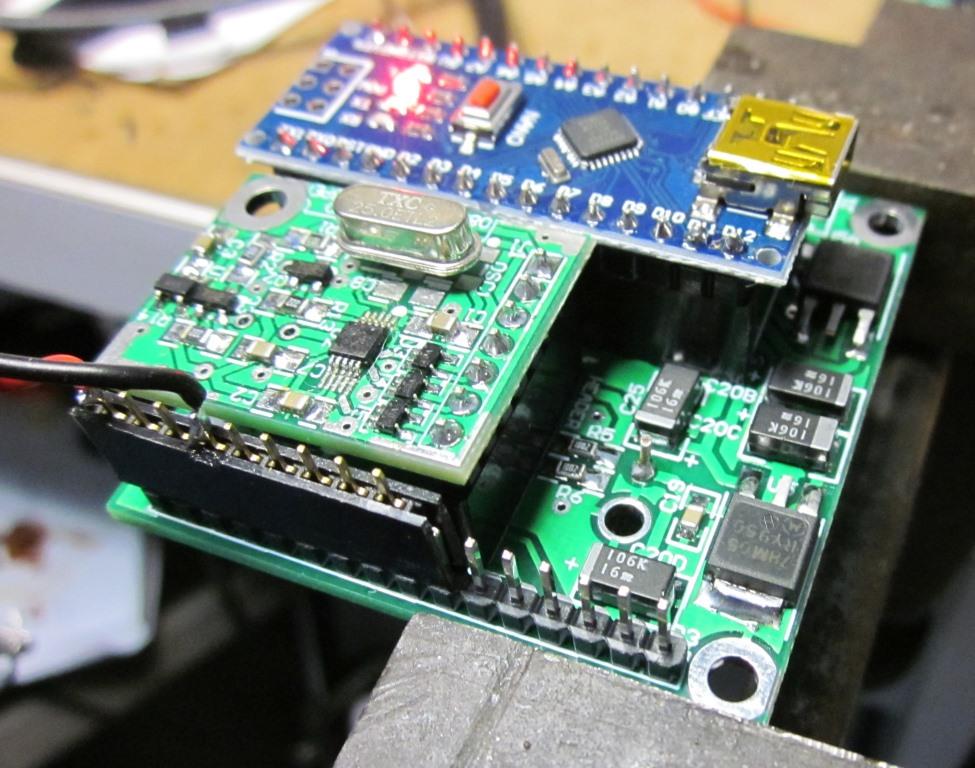 My Si5351 board is shown here plugged into my Raduino clone board. The blue PCB is an Arduino NANO™ board available on eBay™ as a clone or from the original designers from various suppliers.
 The PCB is 50x50mm
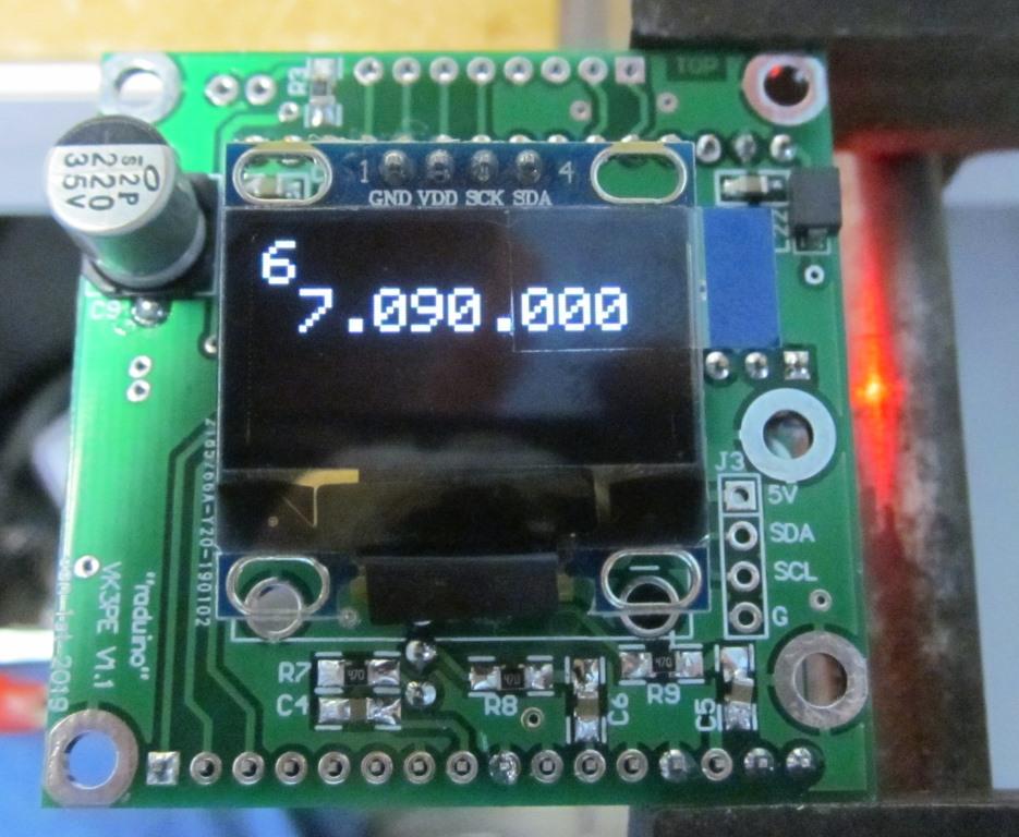
This is the other side of my Raduino clone PCB. It's fitted with a 0.96" OLED display which uses I2C serial protocol, available very cheaply on eBay(™) Other I2C displays could also be used. eg colour displays. The "Raduino" board could be mounted elsewhere with the display only mounted to the panel and a short cable fitted between them. Obviously, the Raduino code is up to the builder. I used a Sketch from VK3HN and partially modified to suit my end usage. I'm NOT an Arduino C++ expert, so please don't ask for my code. My skills if you could call then that, are slightly modifying Arduino Sketches by others much more skilled than I. The Raduino board is 50x50mm in size. On the right side there are 4 holes which allow other I2C devices to be added. eg port expansion using PCF8574.
Not shown is the tuning encoder and various switches etc.
The output level of the Si5351 with the buffers, is approx. +8 to 10dBm at the fundamental as measured on an SA. Note the use of series 47ohm resistors on each of the buffered Si5351 ports in the schematic and visible above as R7, R8 and R9. To drive a level 7 Mixer, a 2-3dB attenuator can be used and is considered desirable to keep 50R impedance. There is a lot of discussion on the WWW about whether square waves or sine waves should be used on a diode mixer. A very good discussion with practical tests is on uTube™ here.
Another potential issue with the Si5351 is the other channels signal is also present in the wanted output. ie crosstalk.
I have also done some testing of my own, using an Si5351 board with and without buffers.
What I found was, the buffered version typically has at least another 10dB suppression of the unwanted signal from the other port. (I only tested ports 0 and 2 in the test)
You can read more detail of the tests in this pdf file.
Here are the schematics and BOM of both PCB's.
Si5351 board Schematic. click here for pdf I used a 25MHz crystal as the reference frequency as shown, but I also made provision on the board to take a small TCXO. [C8 is only fitted if the optional TCXO is used instead of the crystal shown.]
Bill of material (BOM)
My Raduino Clone board Schematic . click here for pdf Note some NANO pins are not bought out to a connector, due to lack of clear PCB space. In the original Raduino board though, these port pins were used to drive an LCD display module, which I am not using, so the "clone" is still fulfilled for function even though those pins are left vacant. If more DIGITAL port pins are required, then port expansion using PCF8574 which is an I2C device.
Bill of material (BOM)
Top & bottom overlays by component values.
The Schematic is a little messy as I just randomly placed all the elements in the Sch file, before doing the PCB.
Glenn, VK3PE
Disclaimer: This information is presented in good faith but not warranted for any purpose whatever.
I have no commercial arangement with any company or person named.