 H/B Version.
  Jerry, W0PWE's build. March 2021
 W6JL's 50 W Power Amplifier
Updated:- August 21, 2023 (Another Builders picture added)
Peter, ON4BDP, has a few spare PCB's for sale in Europe at cost. (I believe version without relays)
Update March 2022, NEW pcb WITH relay switching.
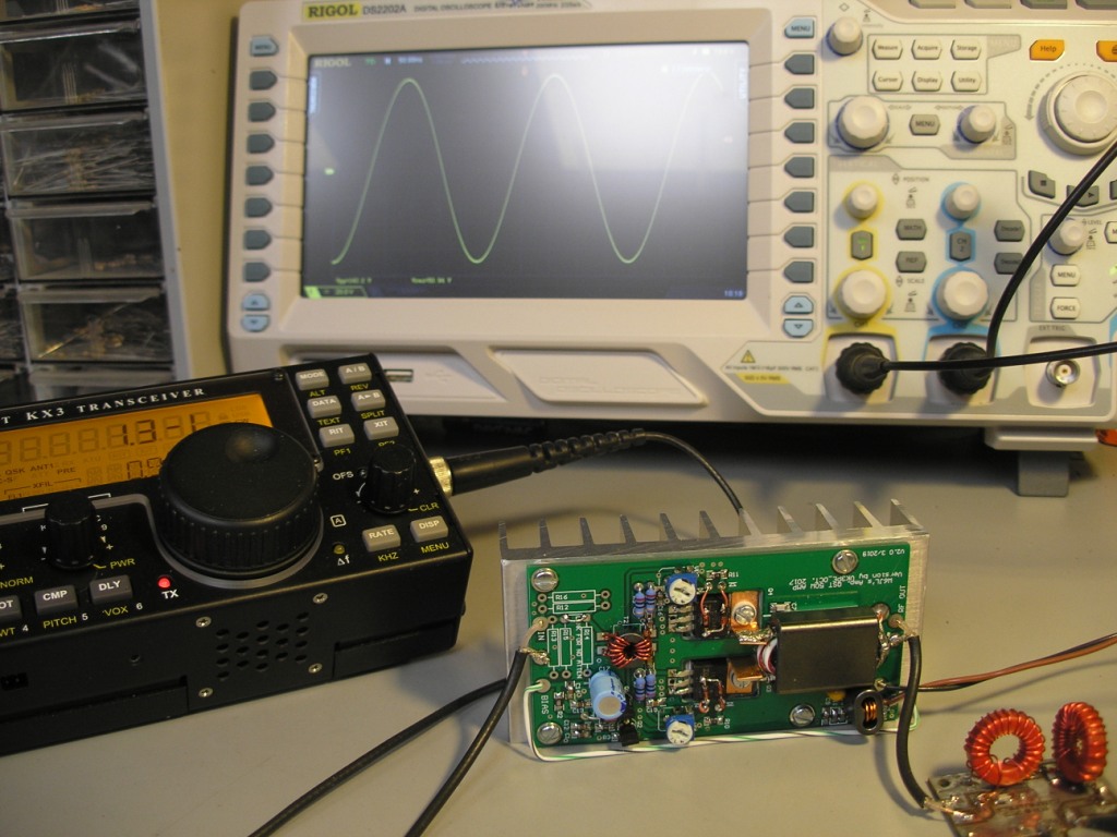
Oct 2020, IRFZ24 and IC-705
Aug 2020 A Sch added.
PCB foils (pdf file actual size, Set print to no scaling, A4 paper size).
NOTE, this is not the PCB shown just below. It's the larger one, further down this page.
My original PCB didn't include any relay switching as used by W6JL. (BUT see here Jan 2022)
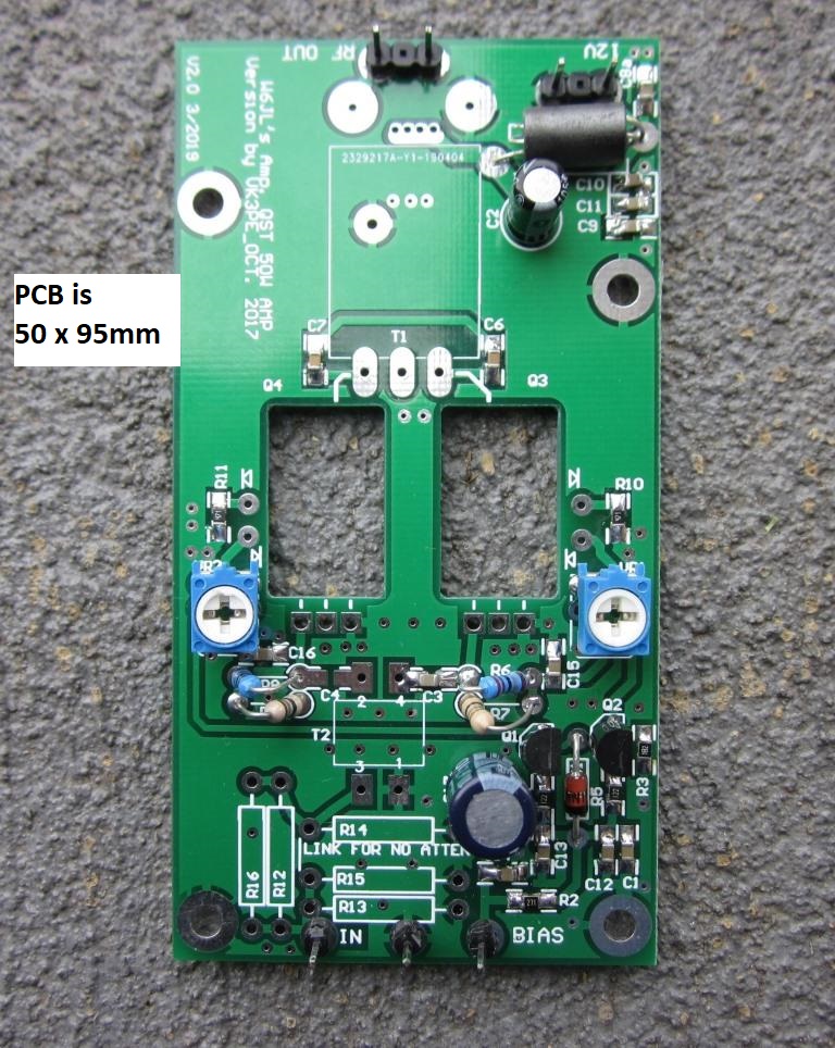
APRIL, 2019:- I have altered the PCB Gerber's a little, so that TWO boards can be made within the typical 100x100mm PCB size limit by the Chinese suppliers. Actual size of each board is 50 x 95mm.
PCB's available.
Jan 2022 :- - I have one spare PCB available, at cost. US$2.00 each, plus $3.90 postage/shipping.
Jerry W0PWE, initially built a W6JL board using home brew construction and later, from my Gerbers. Jerry was very kind to send pictures of his build and reports he is getting 50W out (with ~500mW in) using the IRFZ34N Mosfets. Jerry's project is an AM Tx.
H/B Version. Jerry, W0PWE's build. March 2021
On looking around the Web, many have built a similar amp without using the PCB. eg VK3HN and VK3YY (link on VK3HN's page) for example.
A V2 PCB under construction:-
NEW Feb 2020, BOM added in Xcel or pdf formats. Applies to the PCB shown above.
The original 50W PA design was the winner in the QST Magazine homebrew competition for a home-brew 40M 50W PA to be built under US$125.00. In fact, W6JL, built his winning design for under $30.00 This page is a slight adaption of that design.
http://www.arrl.org/news/the-arrl-second-homebrew-challenge-and-the-winners-areThe details were published in QST™ in June, 2010 and if interested, you will need to chase up a copy of QST as (I assume) it is copyright. The original article and further information is on the QST web pages in the "in-depth" section, but you need to be a member of the ARRL to access this information.
Aug 2020: I found a copy of the original Sch on line here. >> Right Mouse click to save .gif file.
My Sch as per PCB above:- without the relay, and with some minor changes.
The design uses two low cost FET's, type IRFZ24 in the usual push-pull configuration with bias being obtained using a constant current supply and adjustable. Peak power is about 65W at the design centre of 40M but slightly lower power levels are obtained at 80 and 20M. Typically 45-50W. Gain is about 10-12dB.
By the way, the QST web page "in-depth" section mentions even higher gain, in the order of 20dB, being obtainable with some alternate devices. I obtained the IRFZ24 FET's from Farnell™ (now Element14) at about AUD$3.00 each but W6JL says they are available in the USA for under US$1.00 I made a hasty PCB design and had the PCB's made using an eBay vendor at US$63 for 10 boards. (about AU$80) [sorry, no PCB's available] The original design used "Manhattan" construction (no pcb) and had a relay for switching the Amp in and out. I didn't need this feature. I also added provision for an input attenuator. In my haste though, a couple of gremlins got into the PCB so I had to cut a track.
Like most PA's, it must be followed with a suitable low pass filter. W6JL detailed suitable designs but as I wanted to try the Amplifier in my PICASTAR, (home brew HF SDR transceiver designed by G3XJP) as it already has switching and LPF's in it.
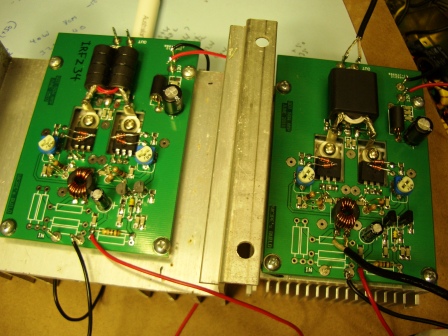
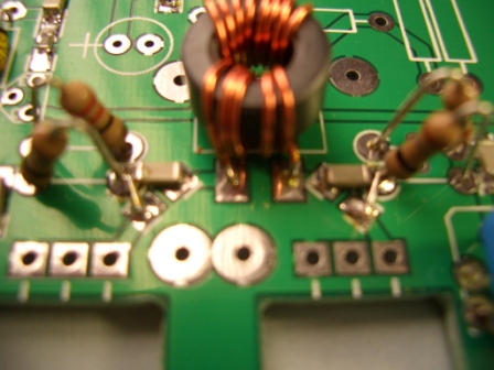
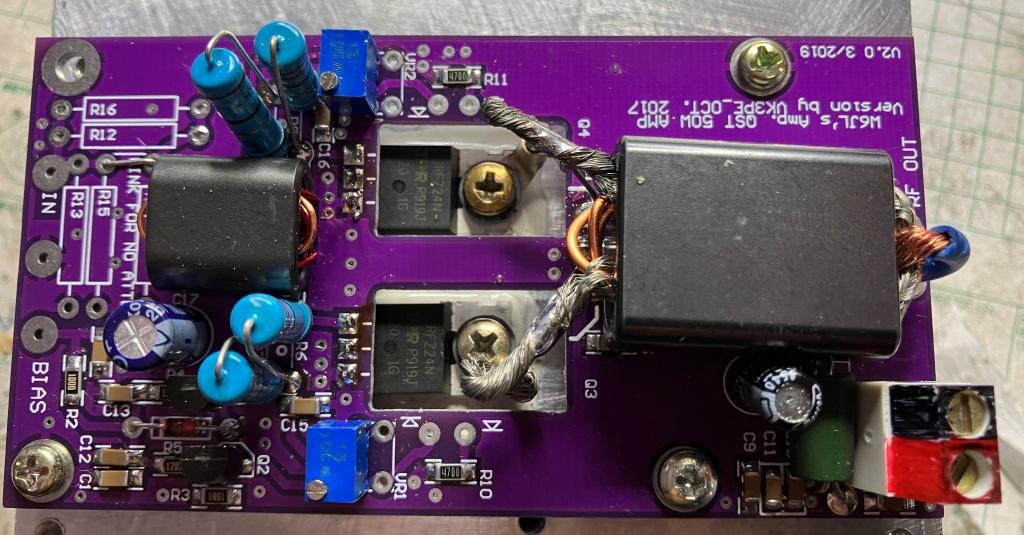
W6JL suggests that IRFZ34's can also be used and better power output will be obtained at 160M also. So, since I had plenty of PCB's I made one of each type although not having the correct output balun core for the IRFZ34 version (version at left in view of both PCB's), I stacked up FT37-43 toroids. At one stage I could see over 80W output at 80M (with no LPF) but the toroids were getting VERY hot ! The input toroid is also an FT37-43 core. You may have noticed the diodes fitted over the FET's. They are used to provide some bias reduction with high temperatures.
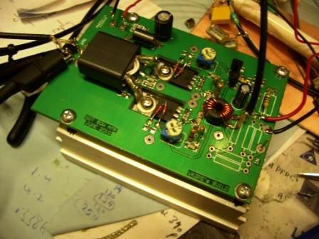
Like all power amplifiers, a good heat sink is required. W6JL used a fan assisted heat sink obtained from a PC. My initial assembly below left, did the same, although the fan is not shown here. The diodes should be used with heat sink paste, not shown here. NOTE: the FET's MUST be insulated from the heat sink, as the tab is not grounded. Use a mica washer or equivalent, plus a bush for insulating the mounting screws. Below is the first PCB I made ie Vers1.0 .
At the top of this page you can see the V2.0 version.
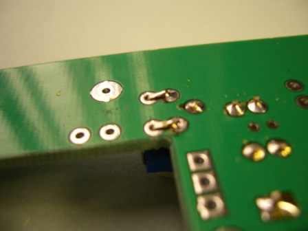
PCB gremlins ! I had to slightly modify the PCB at the gates of the FET's as I had inadvertently placed the coupling caps. in the wrong place ! %*(&(^*&^%&% Likewise, the trim-pots needed to have their leads joined. (The pdf file at top of this page for DIY, has these errors corrected)
2nd August, 2010I ordered another (as specified) ferrite for the output transformer of the IRFZ34 version and have now fitted the PA to my home built Picastar transceiver, based on design by G3XJP.
I did find though, that the input of the amp showed very poor SWR especially over 40M when measured with my N2PK VNA. So, I removed the FT37-43 toroid specified and fitted a BN43-202 wound with 3 (input side) and 2 turns. This gave a much better result. With an input attenuator fitted though, this would be less of an issue. Since the driver amp being used is capable of 20W (G6ALU design) I fitted a 3dB attenuator at the input of the 50W amp. I had designed the PCB with this in mind.On 80M I get an easy 50w output and made several QSO's
< click pictures below for larger view >
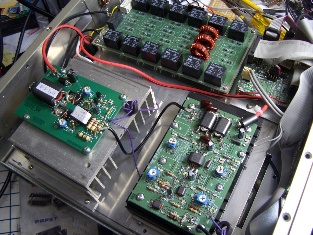
50W to left, G6ALU 20W driver on right, LPF a top.( Only 80M band LPF fitted
in this picture) 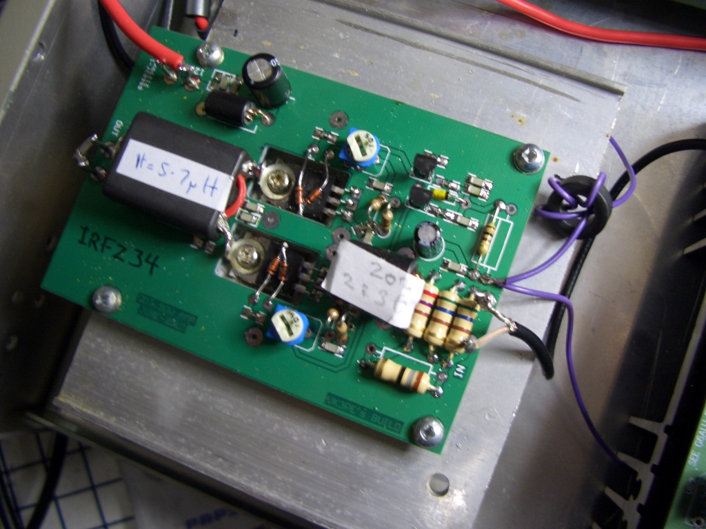
The FET 50W PA board. Note input now uses a BN43-202 Balun core.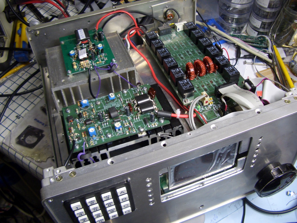
My Picastar all band transceiver (one of 7 I have built). Front panel is temporary, until I fit my colour display.
27th October 2020:- I have now also altered the IRFZ24 amp to use the 3:2 (prim:sec) turn BN43-202 balun at the input with good results also.
I recently bought the new ICOM IC-705 transceiver and will use this amp to get around 50+Watts out for home use. I only plan to use 80, 40 and possibly 20M so an out-board LPF will also be required. I have a 3 band version of the LPF featured on the G6ALU web site and will use that. Possibly with auto band switching.
 W0PWE's build
Below is Peters almost completed build ON4BDP Aug 2023
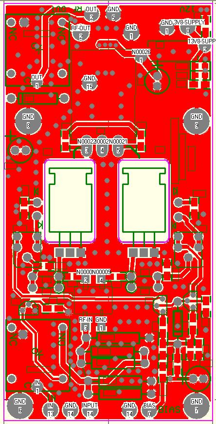
NEW PCB version WITH relay switching.
March 15th 2022:-
I have recently completed 'upgrading' my version of W6JL's Amp incorporating optional RF switching relays, as W6JL did in his original design.
The information is presented here "as is" as I have not yet actually made this PCB. It's heavily based on the version above, but is about 5mm longer. Two can fit onto a 100x100mm panel from Chinese manufacturers. Typically $2-5 plus shipping for 10 panels.
Schematic pdf (new, with better resolution)
Bill of Material pdf
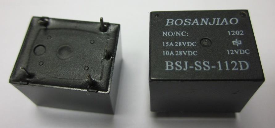
This is the SPDT relay type used. Often also in blue colour, very common type.
PCB overlay by parts value pdf file (part shown as "NPN" is 2N3904 or similar)
NOTE:- you must use a suitable switched (if multi bands) low pass filter following this amplifier.
June 2022:- I have a very limited number of these PCB's available now, at my cost. Email me (see QRZ.COM)
No other info is available. If you would like to get some PCB's made, at your own risk, email me for Gerber files.
Screen shot of the PCB design. The relays are located at top left and bottom left. The PCB is still 50mm wide but is now about 5mm longer, at 100mm. The mounting holes at the 'top' of the PCB have also been moved a little.
Current sense protection?
While it's not happened to me (so far) when a FET blows I have heard it's like a rifle shot going off. Plus of course the 'smoke' is released from the FET.
I noticed that G0KLA has added a current sense circuit to a similar amplifer, to cut bias when the supply current increses too much due to mismatch or other terminal issues. He has a 'sense' reistor in the supply and turns on a transistor if the current is too high, (~3A in this case) which disables the Bias supply. I haven't tried this but those interested might like to check out G0KLA's work here.
Page created on 3rd July, 2010 by VK3PE (e-mail via QRZ.COM)Last updated on August 21, 2023