SINGLE BOARD PICaSTAR
PICaSTAR is a full Multi band HF transceiver designed by G3XJP for home construction. It is NOT a kit !
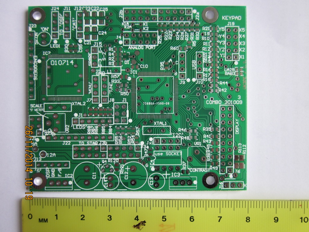
Peter's original design is based on a number of functional PCB modules, wired together. This "Combo" version combines those modules into a single PCB. (Less control and PA's, LPF)
This page is for Version "BB" of the Combo PICaSTAR Panel released in October, 2009. The older version "A" is here.
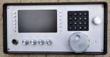
Paul's (M1PVC) Combo under
construction, with TFT display. Click for larger pictures. 1st
QSO ! 17th Oct 2010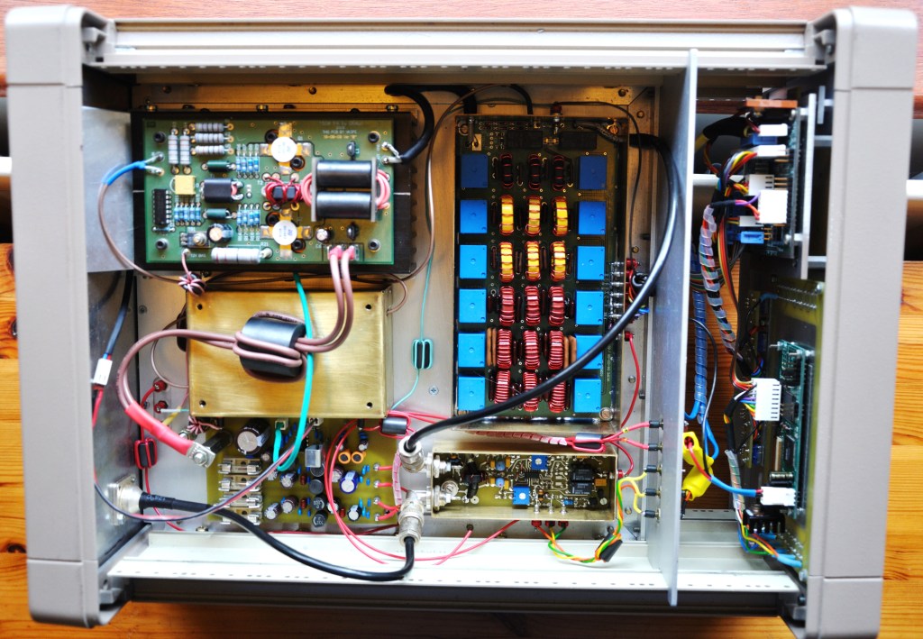
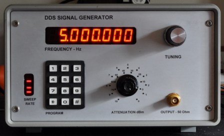
See Paul's signal generator also, made from a Picnmix
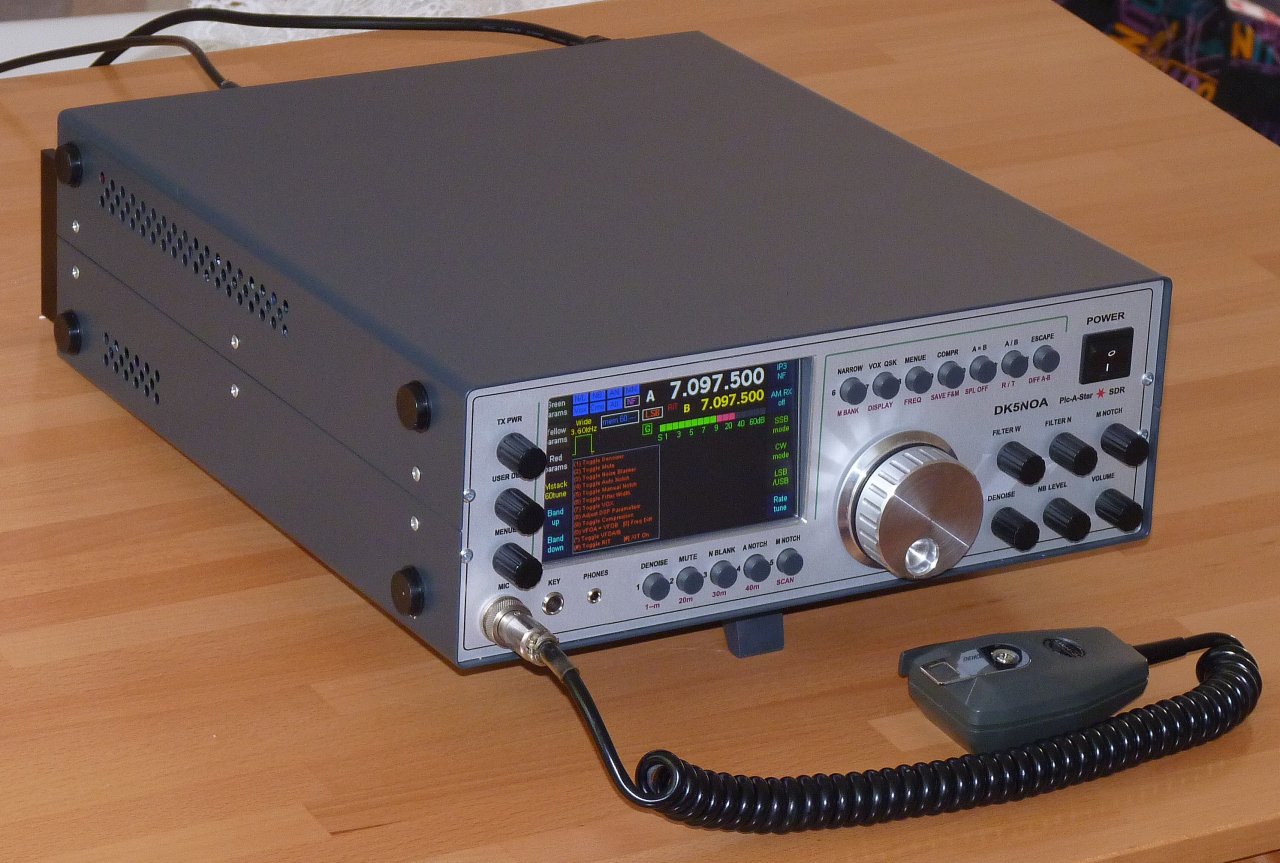 Click for larger Picture of Enno's STAR DK5NOA
G3VPX's TrxAVR Interface web pages.
PICaSTAR
construction information, software, set-up and operational instructions
are available on G3XJP's Picaproject Yahoo Group.
The support group for PICaSTAR is the PICaSTAR-users Yahoo group. The
support group for TrxAVR-PICaSTAR will be the Homebrew-radios Yahoo group.
These pages are for construction of the VK3PE PCB's.
PLEASE READ THIS:- This is a copy of an e-mail sent to some interested people on 21st Oct 2009.
It has full details of the Panel, some pointers to its design and conditions.
The "COMBO" PCB, when assembled correctly, will form a Transceiver based very closely on the PICaSTAR design by G3XJP This is NOT a "kit". The PCB only is supplied and you need to have reasonable construction experience to build this project. You will also need to make or adapt a suitable case for it
You must be a member of the Yahoo "picaproject" group to obtain the Manuals and Software. It is very helpful to also be a member of the "picastar-users" group. If you plan to fit a colour display to your STAR, you should be a member of the "TftA_Central" group also.
Glenn vk3pe
PCB AVAILABILITY
March 2012:-
I am taking expressions of interest in a group buy of the COMBO-STAR Vers 'C2" pcb's. See link below:
Combo Vers "C" PICASTAR NEW October 24th, 2011.
My Combo 'CC' panel is now on the air! This version will incorporate provision for all of Bob Dalley's mods., if you wish to fit them.
If any interest in Trxavrb PCB, please email me. I have a few available
I still have a few Real Time Clock PCB's left.
See what PCB's were included with Combo here.
Enquiries etc: vk3pe @ bigpond.com (remove space either side of "@" symbol) Put "COMBO PCB" as the subject line on e-mail please.
TFT PCB this is the PCB that allows a colour screen to be added to your PICASTAR.
click for Ian's pages.
The TftA pcb is available now. You need to contact Gerard VK3CG, to get the PCB, NOT vk3pe.
Feb 28th, 2010: Suggested Combo PCB assembly method.
Feb 14th Making the shields, a suggested method.
LPF notes added (from my older STAR pages)
Home made case and Lodestone winding
UPDATES TO THIS PAGE:
April 4th, 2011: NEW.... Build pictures by DK5LV
Dec 6th, 2010, Schematic missing Butler Osc. page put back !!!
Combo BB sheet 5 corrected RS232 switch part number on sch only.
Aug 24th Toko coils supplier added (for BPF)
26th Aug, 2010, added Tft build link
July 7th, 2010: Schematic updated so all pages are Landscape mode instead of mixed.
July 2010;- Bob Dalley has made some changes to DDS and IF board
November 26, 2014 Schematics updated info for "L3303" winding and clarify T4-1 connections in MR
April 28, 2010 Possible DDS mods. for better output to MR
3rd April, 2010: ERROR on the PCA9555 pcb. Missing ground on pin 12
March 31st: Combo Sch update, Display wiring and INTEGRATION drawing.
29th, March, 2010: Note at bottom re transistors for the 140W PA added.
March 10th, 2010: TIMER values changed ! BOM, overlay and Schematic updated
Feb 8th 2010: Builder update, F1CHM
21st Jan, 2010 Overlay by value for TrxAVRB corrected
Jan 6th 2010 New builder and BPF curves added.
Jan 2nd 2010: TrxAVRB BOM updated, Schematic and overlay by value added.
31st Dec 2009: BOM updated to version _3b, LED orientation, Build info update, Butler note, BOM's for I2C, Beeper, Ponyprog, added
14 Dec 2009 Build notes added
10th Dec, 2009: New BOM and builders pic added.
Dec 9, 2009: more BPF information added
Dec 5th: My own (VK3PE) build is going well, with receiver now running.
Nov 27th, 2009: overlay by component value added.
Nov 27th. PCB's arrived and have been posted out.
Nov 20th, Schematics tidied up only
Page created on 21st October 2009
Click to enlarge.
 Left:
Michel, F1CHM, Combo PICASTAR (Version A)
Left:
Michel, F1CHM, Combo PICASTAR (Version A) 
On the right is VK3PE's version A radio. Both use PICnMIX display, but updated later to TFT colour.
Single PCB STAR ? What started this off, ideas and thoughts. See the HISTORY here
BUILDER's PAGES click here to see them.
Suggested Combo PCB build method.
Wondering where/how to start? Check here. NEW 27th Feb
To speed up the loading of the PCB, I have the component overlay (pdf) by values, up on my PC and zoom in on an area being loaded. That way you can quickly see the values to be loaded. I find it best to load all of the 100nF caps, then the 10K resistors are they are in the majority. You do need to be organised though with all of the components on the (clean) workbench.
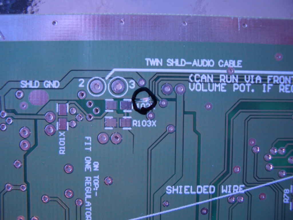
There is a small issue on the underside of the Combo PCB in the CODEC area. A tiny section of copper must be cut. Cut away from the adjacent track, to avoid track damage.
There has been one reported case of a short to ground of the 12v supply in timer area. * a PCB fault *
Pin 12 on the PCA9555 device PCB should be connected to ground. April 1st 2010
Not a problem in the PCB but might catch you out:
The wide band LED mounts on the pcb the reverse direction of all of the other band LED's - Caught me out - might catch others. (Thanks Paul Craven)
Hi Glenn, < 31st Dec, 2009 >
Pretty much finished the Butler osc today on combo. I know I brought this up before but I see that the output cap C306 is still specified at 8.2pF. Peter originally called for a 100nF in series with a 68pF (which is still about 68pF) to feed the AD9951. My experience with Star #1 built on your boards with 8.2pF was low LO output on the higher bands, particularly 10m, measured with an RF power meter. Substituting a 68pF in place of the 8.2pF brought the LO output up to specs on all bands.
Was there a particular reason for changing the value of C306 to 8.2pF? I don't recall anyone else reporting problems with low LO drive but there again maybe no one is currently worrying about 10m??
Jay Cox (click for Jay's build page)
Making the shields, a suggested method. New 14th Jan, 2010
and updated on 17th Feb with info from Dan Rae
Build Notes explaining some items of the PCB assembly ** 15th Jan, 2010 **
And suggested build method, including basic testing Check here.
DDS Filter mods. (unofficial) to increase DDS levels into MR.
NOTE: The changes to the parts required for Bob's Mods. are NOT reflected in the BOM or schematics given here for Combo PICaSTAR.
Bob Dalley wrote: Edited post: Homebrew-radios,
post #5304
Hi All, Some of you will remember my earlier postings
on DDS output levels.
The solution that I chose is to re-work the filter for
50R rather than 200R. This avoids the major signal loss in the filter
termination / Amp. Anyone STARting out could easily incorporate the new
filter and never experience output problems. No changes to the Squarer
are needed, it all Just Works. No extra components need tacking to the
board, just new values for existing parts. It works 110% in my ComboSTAR.
The component values and background for this are all on an evolving page
at: http://www.m0rjd.co.uk/LO.html
Worth a look? If you are building a new STAR and have not shielded everything
it probably is!Regards,
Bob
!st July, 2010:-Bob has also done some detective work on the IF board and found some areas that could be improved with mostly simple value changes; http://www.m0rjd.co.uk/Second-Mixer.html
NOV 2010:-, all Bob's Mods are now indexed here:- http://www.m0rjd.co.uk I have made all of the Mods except the DDS ones, which I intend to do asap. <vk3pe>
INTEGRATION DIAGRAM 280310
This drawing should assist in wiring up (integration) your Combo BB PICaSTAR.
It will print out as FOUR (A4 size) sheets. Tape them together. The drawing is actually from the 'A' version Combo and will vary slightly in pickup points for some wires, but this should be obvious when comparing with the BB board you have.
DISPLAY WIRING 280310
Draft interconnect details for various display types. Character based, 320x240 and 128x64. Colour too.
COMBO "BB" BOM, main PCB only.
ALERT...4th March. I have been advised that the values of R794 & R796 in the timer section, should be changed from 1k to 470R. This only affects builders who use Ian's Peak SWR interface. The present value does not guarantee that a low logic level to the Timer PIC will shut down the PA.
'Line output' transformer: Mouser have the XICON '42TL016-RC' which might be ok. Check dimensions etc on Mouser data sheet. Sept 16th, 2010
Bill of Material Updated, Version "_4" 4th March, 2010
See also here for Mouser Parts Lists NEW 25th FEb 2010 Thanks Bill, N4BKT
Please see notes above re C306 value, in Butler Osc section.
Need a crystal filter? See notes at end of this page.
in VK, MPSH10 transistor is available from http://www.minikits.com.au or eBay
Toko Coils for the BPF:- try Spectrum Communications (UK) www.spectrumcomms.co.uk
Gary Richter has kindly summarised QTY of each part in the build and it's included in BOM above as a guide only.
The Bill of Material Version _2 updated 9th Dec, 2009 Reference only !
NB updated last 2 items 141209
Bill of Material (BOM 231009 vers _1 for reference only) PLEASE IGNORE ref to MPF102 !
Combo "BB" PCB OVERLAY
Component Overlays 231009
Overlay main Combo PCB by parts VALUE updated 9th March, 2010
Combo "BB" PCB SCHEMATIC main PCB only.
** Information on winding L3303 (2N3866 output transformer) is contained in Part 3 of the PICnMIX articles on the "picaproject" Group. It is designated "T1" and is 8 bifilar turns on FT37-43 toroid with 32swg wire
6th Dec, 2010 Schematic (Butler page was missing, now put back)
TrxAVR PCB integration to Combo PICASTAR
The TrxAVR PCB by Ian, G3VPX, (the TrxAVRB PCB on the ComboSTAR panel was designed by Chris Stake) is included on this panel of PCB's and provides a display and user interface for the radio, with software by Ian, G3VPX.
The display can take several forms, multi line character based LCD modules or full graphics LCD with touch screen. Full colour also, when the "tftpcb" is finalised.
Combo PICASTAR PCB has been designed to allow the TrxAVRB PCB to simply be plugged in, in place of the PICnMIX board.
 click for larger picture.
Nov 2014:- A small number of these PCB's are available for builders thinking of adding a colour TFT display to their Classic Star built with original style modules.
Refer here for general info and also to Ian's pages (G3VPX) links above. Includes software details.
SCHEMATIC added 020110
BOM updated 2nd Jan 2009
OVERLAY by component Ref number.
And now by by Component VALUE {Jan 20th, corrected transposition of C55 & R30 values}
If you are going to fit a TFT display, then you may be interested in my build and set-up information here.
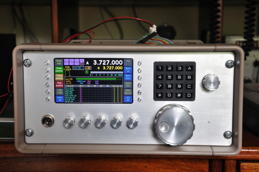
 Paul, M1PVC's, Combo with TFT display. 26/8/10
click for larger picture or see Pauls build here.
If you are going to fit a colour Tft display, then you may be interested in my build and set-up information here.
BOM kindly supplied by Bill, N4BKT, 31st Dec 2009
PONYPROG (programmer interface PCB)
BOM kindly supplied by Bill, N4BKT, 31st Dec 2009
I2C serial pcb (used with TrxAVRB)
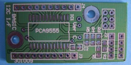
NOTE: pin 12 of the PCA9555 has NO Ground. Solder a wire from pin 12 to GND near the screw hole. You will need to scrape the resist a little first. 1st April, 2010
SCHEMATIC & data sheets etc (ZIP file)
BOM and BOM with Mouser Ref numbers supplied by N4BKT
Refer to Ian's pages for programming details. There is a lot of flexibility here.
Band Pass Filter section.
The BPF is closely based on the original design by G3XJP, but the inductors are now on the top and Lodestone formers can be fitted.
I have some information here and here (coil winding) which may be usefull for coil winding, if using Toko formers.
Toko pre-wound coils are difficult to buy these days but some data here may be helpfull. NEW Feb 2011
Dec 7th, 2009:- I wound Toko formers for 160, 80 and 40M. I found that the 160 & 80M Toko's I used needed some extra turns over the table in the link above, to get a good tuning range. I added 4 turns to both.
Jan 3rd, 2010:- Now fitted some Lodestone formers for 20M and above. See results in link below:
Results so far for my BPF are here. Updated Jan 5th, 2010.
Jan 2nd, 2010 I have some winding information for Lodestone formers.
Lodestone winding:- Check Pauls information here. NEW Jan 2011
Ensure the COTO reed relay is inserted correctly also. (check this page) The PCB will take 2 types of the relay, with either 0.15" or 0.2" pitch leads. The better relay is one with inbuilt diode.
20W PA (Refer to Steve, G6ALU pages for all build information)
* The Epcos core specified is available from RS-Components #212-0594
140W PA G6ALU pages for all build information
VK3PE's build (the version for Combo has no known faults)
Possible alternate PA. 50W FET amp in QST, June 2010 edition. NB. low output above 20M
VK3PE's 50W PA experiments here.
March, 2010: It appears that the SD1487 PA transistors from Burkitts in the UK, have now all been sold. John Birkett's in the UK used to sell the SD1487's. www.zyra.org.uk/birkett.htm
Suitable equivalents are believed to be: (Ref Homebrew-radios, Posts 5001, 5005, 5009 )
MRF454 available from RF Parts (www.rfparts.com) about US$77.90/pr. (MA brand) Available to USA buyers only after April 22nd, 2010 ?
MRF454 available from www.communication-concepts.com for $51.00/pr.
2SC2879-MP (matched pair) from RF Parts about US$68/pr. Builders report good results using these.
HF12-125 from www.spectrumdevices.com (USA) Unsure if they sell direct though. Cost is about $120/pr
HF12-100 is shown as equivalent to SD1487 in data sheets. Cost unknown.
LPF G6ALU pages for all PA & LPF build information
VK3PE build notes NEW 15th Feb, 2010
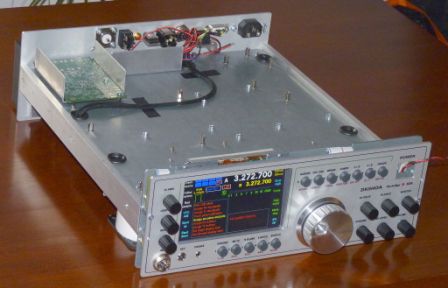
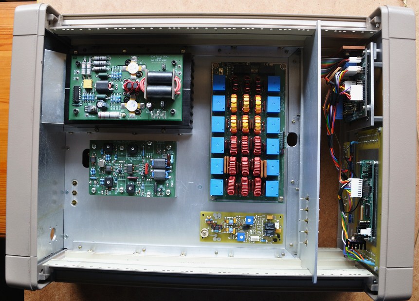
Integration
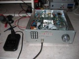
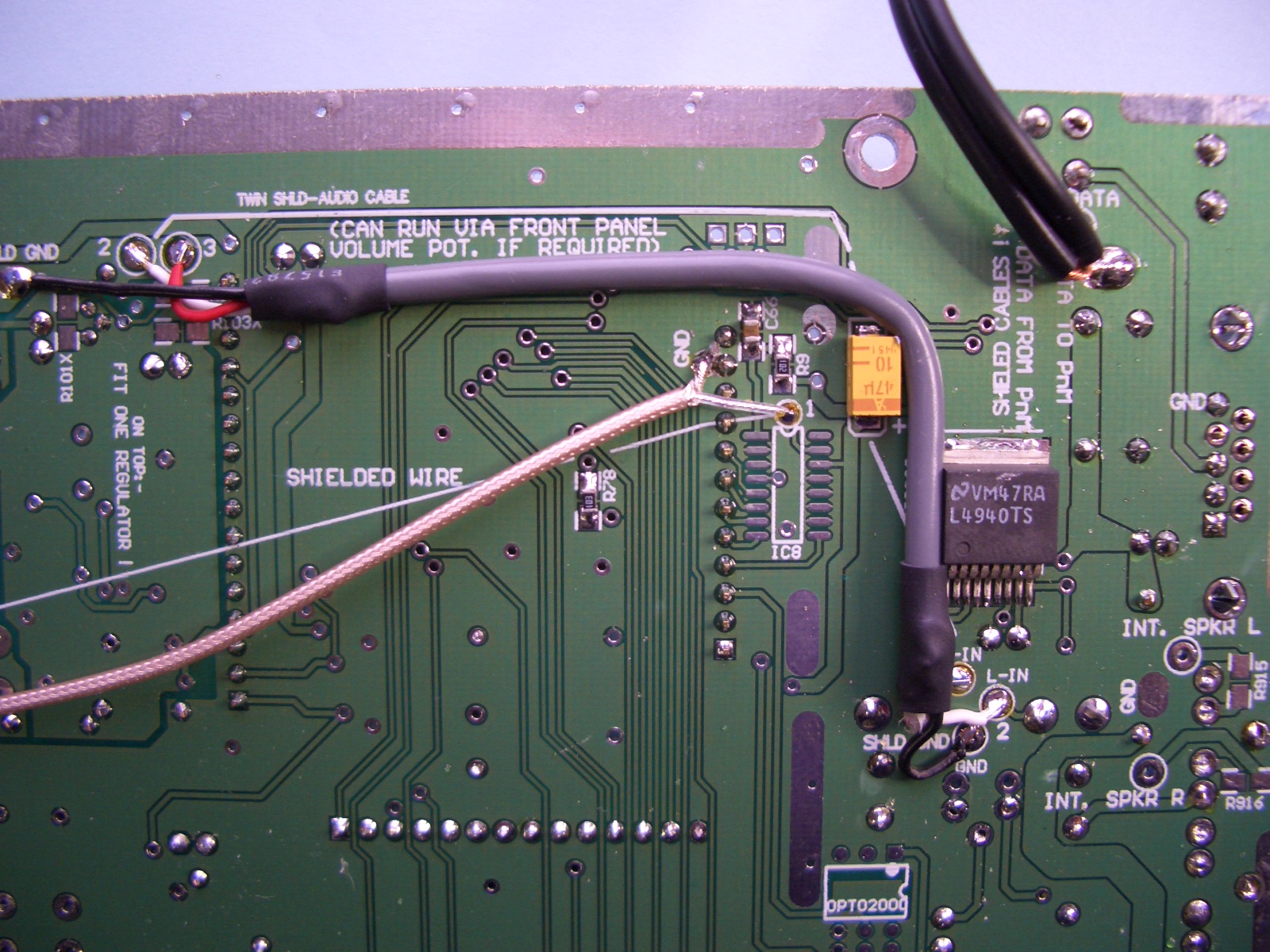
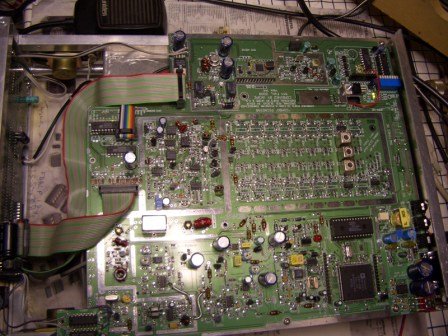
A feature of the COMBO STAR PCB is the ease of assembly. Most wiring between the various sections is on the PCB itself. There are a few coax cables under the PCB for interconnecting RF sections. Wiring to the Picnmix or Trxavrb (front panel) is via two 20 pin IDC cables, quickly and easily made.
Below: Wiring under the PCB consists of some co-ax cables and audio shielded cable (twin shielded). These cables were then hot-melt glued to the PCB. There are also two short co-ax cables on the top, in the 2nd mixer area. (not shown here)
The cable in the top right of the pictures, is the RS232 (serial) cable to the Picnmix board. I used shielded audio cables.
These three pictures are the Version "A" PCB but version "B" is almost identical.
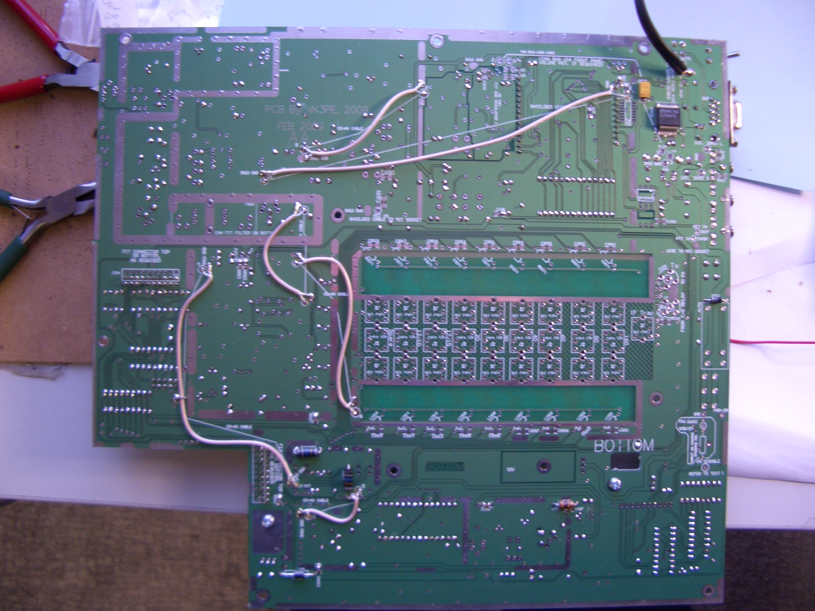
RIBBON CABLES ARE USED TO CONNECT TO TrxavrB PCB and the LPF..
10M4D, 10.695MHz centre
Some older CB radios have these fitted.
Eg Uniden PC122 model. Pearce Simpson ST-901 (Uniden clone)
Also available new from:-
USA
http://www.rfparts.com/serviceparts_galaxy.html
GALXFL-10M4D Crystal filter, 10.695 MHz $28.95
And of course they also sell the RF Mosfets for the 20W PA board.
USA
http://www.rrcom.com/radioparts/Ranger%20Price%20List%202.htm
look down the page for EFX8106952 or 10M4D
which is priced at US$30 plus
shipping.
USA
www.pacific.us.fm/pacific2005/store/index.html
Ranger CB spare filter EFX8106952
their store has changed so you will probably
need to email them and ask for this
part.
GERMANY
http://www.helpert.de/Ubersicht/Quarzfilter/Quarzfilter2/quarzfilter2.html
Unfortunately, the price is with 52EUR very expensive.
ITT Filters: 10.7MHz centre.
10.7MHz +-3.37KHz bandwidth.
These filters come up on eBay from time to time and will fit the VK3PE PCB's.
One vendor is "RFplus" on eBay for example.
NOTE: the 2nd local oscillator crystal frequency should be the IF, plus 15kHz.
Source for AD1885 Codecs.
Try www.farnell.com, also www.utsource.com, www.questcomp.com (USA) eBay,
Created on 13th Oct, 2009.
PANEL:-
1) Combo PCB, a large PCB that contains all of a PICaSTAR except for PA, LPF and Control (TrxAVRB) The COMBO section is about 260mm wide and 285 mm deep. You need about 30mm or so of height above the PCB. The 10M4D style crystal filter is about the highest component. All but a few bypass capacitors and the Audio Amp I.C. are mounted on the top of the PCB.
2) Opto tuning board. This PCB is for those home brewing the tuning encoder as per original PICaSTAR
3) 20W PA, Steve's (G6ALU) proven 20W PA
4) LPF, Ray's (G4TZR) proven LPF design.
5) TrxAVRB control board, basic version as detailed above. (There is NO PICnMIX)
6) Remote USB PCB for TrxAVRB
7) PONYPROG, small PCB to program the Atmel microcontroller devices on the TrxAVRB interface.
8) Beeper, small PCB for 'beeping' out connections, checking for shorts etc. Now with provision for Auto-OFF.
9) I2C Interface PCB. This is a basic version of Ian's serial interface to TrxAVRB, which will allow expansion for those who wish to use other BPF or LPF configurations or add other switching capability to TrxAVRB Due to lack of space, only the PCA9555 driver chip is fitted. You would need to provide ULN2803 driver devices separately. Most easily done with DIP parts, for example.
SEPARATE PCB:
10) 140W PA, Steve's (G6ALU) proven 140W PA NOTE:- NOT supplied for Sept 2010 group buy.
A near identical PCB can be purchased from Communication Concepts in the USA. They have all components also.
Peter, VK3BPN Feb 12th, Peter had a QSO with VK3PE on 80M < Combo to Combo> 16th March, 2010: Pictures of complete home brew case also.
Glenn, VK3PE This page updated often < eg 22nd Feb, showing 4.3" TFT and now 5" TFT>
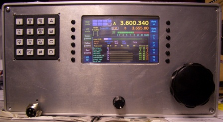 Rig with 4.3" TFT is on air with a number of QSO's. Now has 5"
fitted.
Rig with 4.3" TFT is on air with a number of QSO's. Now has 5"
fitted.
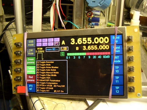 March 2010:
The TRx development group has now finalised a "TftA" PCB which
allows a TFT display to be used with Trxavrb. This 5" type was recently
found and looks good. < click for larger size > Photo does not do
the screen justice. It is excellent and about to be fitted to VK3PE's
ComboStar. (see link above) The TftA PCB is available from Gerard..
March 2010:
The TRx development group has now finalised a "TftA" PCB which
allows a TFT display to be used with Trxavrb. This 5" type was recently
found and looks good. < click for larger size > Photo does not do
the screen justice. It is excellent and about to be fitted to VK3PE's
ComboStar. (see link above) The TftA PCB is available from Gerard..
Dave, M5TXJ Updated June 29th, March 16th, 1st QSO made ! < Dave has his own web page here. >
Seamus, G7ITT Feb 25 is RECEIVING now ! Check link as updated Nov 2010 with pictures.
Dan, ac6ao / g3ncr 4th Jan, 2010. Integration into a nice case: 2nd March, 2010
Steve, G6ALU. 25th jan
Paul, M1PVC 26th Jan < Vintage Collins gear > updated 4th Jan, Lodestone winding info
Paul, M1PVC made 1st QSO, Oct, 200 on his Combo Star, with 5" TFT display. 17th Oct, 2010
See Paul's signal generator also, made from a Picnmix
Jay's Combo 29th Jan, 2010
Charles, VK3NX updated 24th Feb 2010, home built case with excellent integration work.
Michel, F1CHM has fitted a PA3AKE based BPF to Star. 8th Feb, 2010
Michel, F1CHM, is in the TFT team also and now has a 5" TFT fitted to three PICaStars. 28th Nov, 2010
Bill, N4BKT, is in the middle of fitting PCB to a second hand case found at flea market. Pictures are from Bill's own web page blog. Check link for more info and pictures. 25th Feb, 2010. Bill has a Blog here that includes info on his build and also Mouser™ parts lists for easy buying in the USA.
Chris, GM4YLN's, Combo PICaSTAR build page 6th April, 2010
Peter's build, VK3ATC July 22nd 2010
Gerald, VK3GJM, now has his Combo board receiving, after a few weeks of assembly.NEW, 28th Sept, 2010
PIC-a-STAR build by Enno, DK5NOA NEW Page. Check out Enno's inspiring build.
Franck, F1SSF's Combo star NEW Aug 2011
Roy, F5VJM's three Picastars, 2 home brew PCB's, one Combo. NEW Sept 2011
Cristi's nice build NEW 26th Mar 2012
Space for you here ! Send me your build pictures and I will make a special page just for you.
Others are also well advanced on build, but no pictures as yet.
PICaSTAR Builders:
Krzysztof, sp6tpf is building a Picastar using the 'original' modules. Very nice work. Feb 16th 2010
Roderick, VK3YC made his first QSO (to VK3PE) on his Star, Feb 2010
Józef, SP9HVW has made a superb build of his PICaSTAR March 8th, 2010
Sandor, HA2NJ has built Picastar and Picatune 4th May 2010
DK5LV, Hennings PICASTAR Build. April, 2011 NEW
Calvin, M1EPM, has now finished his STAR NEW 29th April, 2011
Pete's 4 year build NEW April 2012
Sanyi HA2NJ has updated his STAR with Trxavrb and TFT NEW 13th May 2012
SP9HVW's
build. Very nice. This is a link to his web page. June 2011.
Some buyers of my previous PCB's have commented about various PCB problems in the panels such as track problems, some hole sizes being incorrect etc. Keep in mind that the design has been made to try to use parts that I think may be available all over the world. It is very difficult for me to actually check that this is fact, but I do put a lot of work into that side of things, not to mention many hundreds of hours into the PCB design itself. No point using a "junkbox" part that nobody can actually buy for example. Sometimes though, parts may be difficult to multi-source. Some have commented about the "funny" pad sizes for resistors and capacitors. The outline for the majority of parts was designed to accommodate as many SMD sizes as possible, including 1206, 0805, 0603 and even 0402. This is to allow builders to use new or surplus parts from a number of sources.
These PCB's are a labour of love. This is not a commercial operation. I am simply trying to help out those who prefer to use a commercially made PCB for various reasons. This is a hobby and only a part time one at that, mistakes may happen, errors may occur, as I do not have the luxury of proving a PCB like commercial manufacturers do, with small pilot runs etc. <VK3PE>
Back to:
Combo AA (proto "Combo")
Last update: November 26, 2014